
Page 211 - Sensors and Control Systems in Manufacturing
P. 211
172
T h ree
Cha p te r
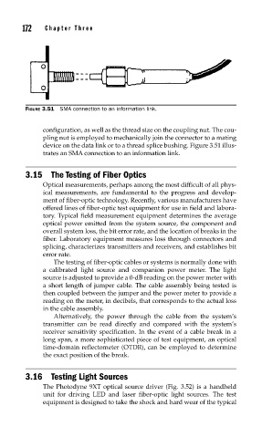
FIGURE 3.51 SMA connection to an information link.
configuration, as well as the thread size on the coupling nut. The cou-
pling nut is employed to mechanically join the connector to a mating
device on the data link or to a thread splice bushing. Figure 3.51 illus-
trates an SMA connection to an information link.
3.15 The Testing of Fiber Optics
Optical measurements, perhaps among the most difficult of all phys-
ical measurements, are fundamental to the progress and develop-
ment of fiber-optic technology. Recently, various manufacturers have
offered lines of fiber-optic test equipment for use in field and labora-
tory. Typical field measurement equipment determines the average
optical power emitted from the system source, the component and
overall system loss, the bit error rate, and the location of breaks in the
fiber. Laboratory equipment measures loss through connectors and
splicing, characterizes transmitters and receivers, and establishes bit
error rate.
The testing of fiber-optic cables or systems is normally done with
a calibrated light source and companion power meter. The light
source is adjusted to provide a 0-dB reading on the power meter with
a short length of jumper cable. The cable assembly being tested is
then coupled between the jumper and the power meter to provide a
reading on the meter, in decibels, that corresponds to the actual loss
in the cable assembly.
Alternatively, the power through the cable from the system’s
transmitter can be read directly and compared with the system’s
receiver sensitivity specification. In the event of a cable break in a
long span, a more sophisticated piece of test equipment, an optical
time-domain reflectometer (OTDR), can be employed to determine
the exact position of the break.
3.16 Testing Light Sources
The Photodyne 9XT optical source driver (Fig. 3.52) is a handheld
unit for driving LED and laser fiber-optic light sources. The test
equipment is designed to take the shock and hard wear of the typical