
Page 324 - Sensors and Control Systems in Manufacturing
P. 324
Angular Displacement, Observed
Encoder Ring Advanced Sensors in Pr ecision Manufacturing 281
Computed Value,
Degrees Pattern Degrees
1 (innermost) 180 1 180
2 90 0
3 45 0
4 22.5 1 22.5
5 11.25 0
6 5.625 1 5.625
7 2.8125 1 2.8125
8 1.40625 0 210.94
TABLE 6.1 Absolute Optical Encoder
Equidistant
sectors
Fixed reading
device
Shaft
Disc
Turn
Strip
Coupling
Linear movement
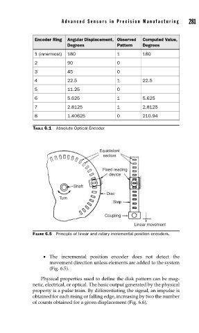
FIGURE 6.5 Principle of linear and rotary incremental position encoders.
• The incremental position encoder does not detect the
movement direction unless elements are added to the system
(Fig. 6.5).
Physical properties used to define the disk pattern can be mag-
netic, electrical, or optical. The basic output generated by the physical
property is a pulse train. By differentiating the signal, an impulse is
obtained for each rising or falling edge, increasing by two the number
of counts obtained for a given displacement (Fig. 6.6).