
Page 375 - Sensors and Control Systems in Manufacturing
P. 375
330
Cha p te r
Se v e n
into two groups: (1) low-temperature sensors with a range of –100
to +400°C using specific sensing materials such as phosphors, semi-
conductors, and liquid crystals, and (2) high-temperature sensors
with a range of 500 to 2000°C based on blackbody radiation.
7.3.1 Semiconductor Absorption Sensors
Many of these sensors can be located up to 1500 m away from the
optoelectronic instruments. The operation of semiconductor temper-
ature sensors is based on the temperature-dependent absorption of
semiconductor materials. Because the energy and gap of most semi-
conductors decrease almost linearly with increasing temperature T,
the band-edge wavelength λ (T) corresponding to the fundamental
g
optical absorption shifts toward longer wavelengths at a rate of about
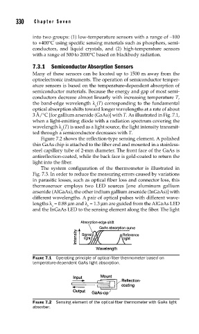
3 Å/°C [for gallium arsenide (GaAs)] with T. As illustrated in Fig. 7.1,
when a light-emitting diode with a radiation spectrum covering the
wavelength λ (T) is used as a light source, the light intensity transmit-
g
ted through a semiconductor decreases with T.
Figure 7.2 shows the reflection-type sensing element. A polished
thin GaAs chip is attached to the fiber end and mounted in a stainless-
steel capillary tube of 2-mm diameter. The front face of the GaAs is
antireflection-coated, while the back face is gold-coated to return the
light into the fiber.
The system configuration of the thermometer is illustrated in
Fig. 7.3. In order to reduce the measuring errors caused by variations
in parasitic losses, such as optical fiber loss and connector loss, this
thermosensor employs two LED sources [one aluminum gallium
arsenide (AlGaAs), the other indium gallium arsenide (InGaAs)] with
different wavelengths. A pair of optical pulses with different wave-
lengths λ = 0.88 μm and λ = 1.3 μm are guided from the AlGaAs LED
s r
and the InGaAs LED to the sensing element along the fiber. The light
FIGURE 7.1 Operating principle of optical-fi ber thermometer based on
temperature-dependent GaAs light absorption.
FIGURE 7.2 Sensing element of the optical-fi ber thermometer with GaAs light
absorber.