Page 487 - Sensors and Control Systems in Manufacturing
P. 487

440
                                    Ni ne
                           Cha p te r

                                                 Program
                                           RAM            ROM
                         Keyboard                                        Display
                                          memory         memory


                                            Data address control bus

                                   0                                 0
                                   1                                 1
                                   2                                 2
                        Sensors                                              Actuators
                                   3              Micro-             3
                                   4             processor           4
                                   5                                 5
                                   6                                 6
                                   7                                 7
                                Input register                  Onput register
                                  (port I)                        (port O)
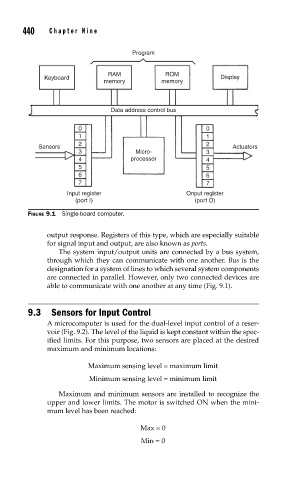
                     FIGURE 9.1  Single-board computer.

                          output response. Registers of this type, which are especially suitable
                          for signal input and output, are also known as ports.
                             The system input/output units are connected by a bus system,
                          through which they can communicate with one another. Bus is the
                          designation for a system of lines to which several system components
                          are connected in parallel. However, only two connected devices are
                          able to communicate with one another at any time (Fig. 9.1).


                     9.3  Sensors for Input Control
                          A microcomputer is used for the dual-level input control of a reser-
                          voir (Fig. 9.2). The level of the liquid is kept constant within the spec-
                          ified limits. For this purpose, two sensors are placed at the desired
                          maximum and minimum locations:

                                     Maximum sensing level = maximum limit
                                      Minimum sensing level = minimum limit

                             Maximum and minimum sensors are installed to recognize the
                          upper and lower limits. The motor is switched ON when the mini-
                          mum level has been reached:

                                                    Max = 0
                                                    Min = 0
   482   483   484   485   486   487   488   489   490   491   492