
Page 489 - Sensors and Control Systems in Manufacturing
P. 489
442
Cha p te r
Ni ne
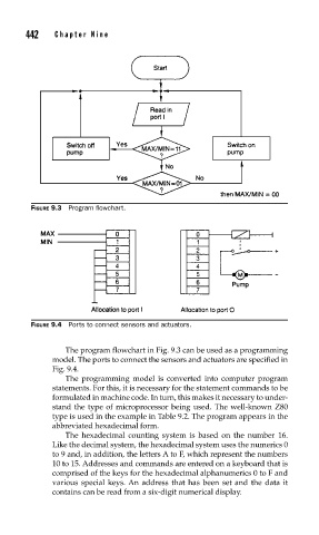
FIGURE 9.3 Program fl owchart.
FIGURE 9.4 Ports to connect sensors and actuators.
The program flowchart in Fig. 9.3 can be used as a programming
model. The ports to connect the sensors and actuators are specified in
Fig. 9.4.
The programming model is converted into computer program
statements. For this, it is necessary for the statement commands to be
formulated in machine code. In turn, this makes it necessary to under-
stand the type of microprocessor being used. The well-known Z80
type is used in the example in Table 9.2. The program appears in the
abbreviated hexadecimal form.
The hexadecimal counting system is based on the number 16.
Like the decimal system, the hexadecimal system uses the numerics 0
to 9 and, in addition, the letters A to F, which represent the numbers
10 to 15. Addresses and commands are entered on a keyboard that is
comprised of the keys for the hexadecimal alphanumerics 0 to F and
various special keys. An address that has been set and the data it
contains can be read from a six-digit numerical display.