
Page 532 - Sensors and Control Systems in Manufacturing
P. 532
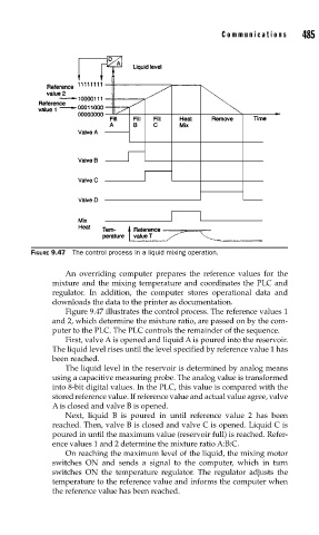
FIGURE 9.47  The control process in a liquid mixing operation.  Communications   485

                             An overriding computer prepares the reference values for the
                          mixture and the mixing temperature and coordinates the PLC and
                          regulator. In addition, the computer stores operational data and
                          downloads the data to the printer as documentation.
                             Figure 9.47 illustrates the control process. The reference values 1
                          and 2, which determine the mixture ratio, are passed on by the com-
                          puter to the PLC. The PLC controls the remainder of the sequence.
                             First, valve A is opened and liquid A is poured into the reservoir.
                          The liquid level rises until the level specified by reference value 1 has
                          been reached.
                             The liquid level in the reservoir is determined by analog means
                          using a capacitive measuring probe. The analog value is transformed
                          into 8-bit digital values. In the PLC, this value is compared with the
                          stored reference value. If reference value and actual value agree, valve
                          A is closed and valve B is opened.
                             Next, liquid B is poured in until reference value 2 has been
                          reached. Then, valve B is closed and valve C is opened. Liquid C is
                          poured in until the maximum value (reservoir full) is reached. Refer-
                          ence values 1 and 2 determine the mixture ratio A:B:C.
                             On reaching the maximum level of the liquid, the mixing motor
                          switches ON and sends a signal to the computer, which in turn
                          switches ON the temperature regulator. The regulator adjusts the
                          temperature to the reference value and informs the computer when
                          the reference value has been reached.