
Page 95 - Separation process engineering
P. 95
62) but written for vapor and liquid 1 must be used (Chien, 1994). Process simulators can do these
calculations (e.g., problem 2.G5), but the equilibrium correlations, particularly the liquid-liquid
equilibrium correlations, need to be checked against data.
2.9 Size Calculation
Once the vapor and liquid compositions and flow rates have been determined, the flash drum can be
sized. This is an empirical procedure. We will discuss the specific procedure first for vertical flash
drums (Figure 2-1) and then adjust the procedure for horizontal flash drums.
Step 1. Calculate the permissible vapor velocity, u perm ,
(2-64)
u perm is the maximum permissible vapor velocity in feet per second at the maximum cross-sectional area.
ρ and ρ are the liquid and vapor densities. K drum is in ft/s.
L
v
K drum is an empirical constant that depends on the type of drum. For vertical drums the value has been
correlated graphically by Watkins (1967) for 85% of flood with no demister. Approximately 5% liquid
will be entrained with the vapor. Use of the same design with a demister will reduce entrainment to less
than 1%. The demister traps small liquid droplets on fine wires and prevents them from exiting. The
droplets then coalesce into larger droplets, which fall off the wire and through the rising vapor into the
liquid pool at the bottom of the flash chamber. Blackwell (1984) fit Watkins’ correlation to the equation
(2-65)
where and const = 1.0 ft/s,
with W and W being the liquid and vapor flow rates in weight units per hour (e.g., lb/h). The constants
L
v
are (Blackwell, 1984):
A = –1.877478097
B = –0.8145804597
C = –0.1870744085
D = –0.0145228667
E = –0.0010148518
The resulting value for K drum typically ranges from 0.1 to 0.35.
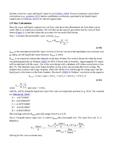
Step 2. Using the known vapor rate, V, convert u perm into a horizontal area. The vapor flow rate, V, in
lbmol/h is
Solving for the cross-sectional area,