
Page 96 - Separation process engineering
P. 96
(2-66)
For a vertical drum, diameter D is
(2-67)
Usually, the diameter is increased to the next largest 6-in. increment.
Step 3. Set the length/diameter ratio either by rule of thumb or by the required liquid surge volume. For
vertical flash drums, the rule of thumb is that h total /D ranges from 3.0 to 5.0. The appropriate value of
h /D within this range can be found by minimizing the total vessel weight (which minimizes cost).
total
Flash drums are often used as liquid surge tanks in addition to separating liquid and vapor. The design
procedure for this case is discussed by Watkins (1967) for petrochemical applications. The height of the
drum above the centerline of the feed nozzle, h , should be 36 in. plus one-half the diameter of the feed
v
line (see Figure 2-14). The minimum of this distance is 48 in.
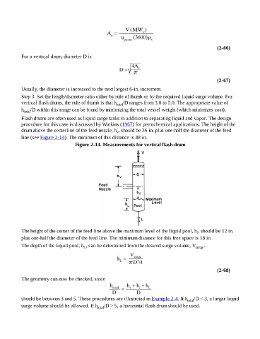
Figure 2-14. Measurements for vertical flash drum
The height of the center of the feed line above the maximum level of the liquid pool, h , should be 12 in.
f
plus one-half the diameter of the feed line. The minimum distance for this free space is 18 in.
The depth of the liquid pool, h , can be determined from the desired surge volume, V surge .
L
(2-68)
The geometry can now be checked, since
should be between 3 and 5. These procedures are illustrated in Example 2-4. If h /D < 3, a larger liquid
total
surge volume should be allowed. If h total /D > 5, a horizontal flash drum should be used.