
Page 129 - Shale Shakers Drilling Fluid Systems
P. 129
112 SHALE SHAKERS AND DRILLING FLUID SYSTEMS
of a linear motion shaker. Line size and potential The disadvantage of this design is the limited
head losses must be considered with this arrange- visibility of the upper and lower screens, due
ment to avoid overflow and loss of drilling fluid. to the height of the scalper shaker and the min-
This design may reduce overall cost by using ex- imum clearance between the upper and lower
isting equipment. This concept, where space is shakers. On some models, it is also difficult to
available, has the advantages of highly visible perform routine maintenance and replace vibratory
screening surfaces and ease of access for repairs. drive components.
The disadvantage of separate individual shakers is
the space needed for mounting the shakers and
the extra piping needed to tie the scalping shak- The integral Unit with a Single
ers to the flow-line shakers. Vibratory Motion
This design consists of an integral unit with a
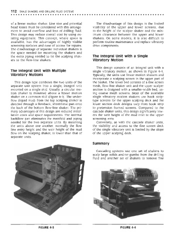
The integral Unit with Multiple single vibratory motion, as shown in Figure 4-4.
Vibratory Motions Typically, the units use linear motion shakers and
incorporate a scalping screen in the upper part of
This design type combines the two units of the the basket. The lower bed consists of a fine screen
separate unit system into a single, integral unit mesh, flow-line shaker unit and the upper scalper
mounted on a single skid. Usually, a circular mo- section is designed with a smaller-width bed, us-
tion shaker is mounted above a linear motion ing coarse mesh screens. Most of the available
shaker on a common skid (Figure 4-3). The under- single vibratory motion shakers use hook strip-
flow (liquid mud) from the top scalping shaker is type screens for the upper scalping deck and the
directed through a flowback, sheetmetal pan onto lower section deck designs vary from hook strip
the back of the bottom flow-line shaker. The pri- to pretension framed screens. Compared to the
mary advantages of this design are reduced instal- cascade shaker units, this design significantly low-
lation costs and space requirements. The internal ers the weir height of the mud inlet to the upper
backflow pan eliminates the manifold and piping screening area.
needed for the two separate units. By mounting Conversely, as with the cascade shaker units,
the units above one another, normally the flow the visibility and access to the fine screen deck
line entry height and the weir height of the mud of the single vibratory unit is limited by the slope
flow on the scalping shaker, is lower than that of of the upper scalping deck.
separate units.
Summary
Cascading systems use one set of shakers to
scalp large solids and/or gumbo from the drilling
fluid and another set of shakers to remove fine
FIGURE 4-3 FIGURE 4-4