
Page 132 - Shale Shakers Drilling Fluid Systems
P. 132
CHAPTE R FIV E
Shaker User's Guide
All solids removal systems should have enough
shale shakers to process 100% of the drilling fluid
circulating rate. For expensive wells, an evaluation
should be conducted to determine the drilling fluid
processing system needed to minimize drilling
and disposal costs. On the basis of this evaluation,
the number, type, and configuration of shaker(s)
can be chosen (see Selecting Shaker Screens dis-
cussed in Chapter 4). The following guidelines FIGURE 5-1
address the installation, operation, and mainte-
nance of shale shakers.
INSTALLATION
In all cases, the owner's manual should be
consulted for proper installation procedures. If
unavailable, the general guidelines below may
be helpful: FIGURE 5-2
1. Low places in the flow line will trap cuttings.
The flow-line angle should be such that sol-
ids settling does not occur. In general, estab-
lish a 1-inch drop for every 10 feet of flow line.
2. When using a back tank, also known as a
possum belly, the flow line should enter the
bottom to prevent solids from settling and
accumulating. If the flow line enters the top
of the back tank, it should be extended to
within one pipe diameter of the flow line FIGURE 5-3
from the bottom.
3. Rig up with sufficient space and approved
walkways around the shaker(s) to permit
easy maintenance. An optional top delivery (Figure 5-3) prevents
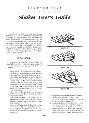
4. Branch tees, Figure 5-1, should be avoided. cuttings from settling in the back tank.
Solids preferentially travel in a straight path A cement bypass that discharges outside
resulting in uneven solids distribution to the the active system is desirable.
shale shakers. Mount and operate the shale shaker where
5. Ensure equal fluid and solids distribution when it is level. Otherwise, both the solids and
more than one shaker is used (Figure 5-2). fluid limits will be reduced.
6. Options shown in Figures 5-2 and 5-3 are 10. Motors and starters should be explosion-
better than the distribution system shown in proof. Local electrical codes must be met. Be
Figure 5-1. sure the proper sized starter heaters are used.
115