
Page 128 - Shale Shakers Drilling Fluid Systems
P. 128
SHAKER APPLICATIONS 111
rigs. The cost of handling discarded material may still remains only one component of a complete
require drying the discard. The fine mesh screens drilled solids removal system (see Chapter 7).
discharge much wetter solids than those discarded A system of cascading shale shakers is de-
from very coarse screens (see Chapter 13). signed to use one set of screens (or shakers) to
scalp large solids and gumbo from the drilling
fluid, and another set of lower screens (or shak-
CASCADE SYSTEMS ers) to receive the upper shaker underflow fluid for
removal of fine solids. This combination increases
The first cascade system was introduced to the solids removal efficiency of high performance
the drilling industry in the mid-1970s. A scalper shakers, especially during fast, top-hole drilling or
shaker received fluid from the flow line and re- in gumbo-producing formations. The cascade sys-
moved gumbo, or large drilled solids, before the tem is used where the solids' loading exceeds the
fluid passed through the main shaker using a fine capacity of the fine mesh screen. The advantages
mesh screen (at this time, 80- to 120-mesh screens of this cascade arrangement include:
were the practical limits). The first unit combined
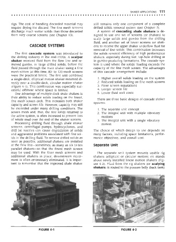
a single-deck, elliptical motion shaker mounted di- 1. Higher overall solids loading on the system
rectly over a double-deck, circular motion shaker 2. Reduced solids loading on fine mesh screens
(Figure 4-1). This combination was especially suc- 3. Finer screen separations
cessful offshore where space is limited. 4. Longer screen life
One advantage of multiple-deck shale shakers is 5. Lower fluid well costs
their ability to reduce solids loading on the lower, There are three basic designs of cascade shaker
fine mesh screen deck. This increases both shaker systems:
capacity and screen life. However, capacity may still
be exceeded under many drilling conditions. The 1. The separate unit concept
screen mesh and, thus, the size solids returned to 2. The integral unit with multiple vibratory
the active system, is often increased to prevent loss motions
of whole mud over the end of the shaker screens. 3. The integral unit with a single vibratory
Processing drilling fluid through shale shaker motion
screens, centrifugal pumps, hydrocyclones, and
drill bit nozzles can cause degradation of solids The choice of which design to use depends on
and aggravated problems associated with fine sol- many factors, including space limitations, perfor-
ids in the drilling fluid. To remove drilled solids as mance objectives, and overall cost.
soon as possible, additional shakers are installed
at the flow line—sometimes, as many as six to ten Separate Unit
parallel shakers—so that the finest mesh screen
may be used. With the finer mesh screens and The separate unit system mounts usable rig
additional shakers in place, downstream equip- shakers (elliptical or circular motion) on stands
ment is often erroneously eliminated. It is impor- above newly installed linear motion shakers (Fig-
tant to remember that the improved shale shaker ure 4-2). Fluid from the rig shakers (or scalping
shakers) is routed to the possum belly (back tank)
FIGURE 4-1 FIGURE 4-2