Page 204 - Shigley's Mechanical Engineering Design
P. 204

bud29281_ch04_147-211.qxd  11/27/09  2:55PM  Page 179 ntt 203:MHDQ196:bud29281:0073529281:bud29281_pagefiles:


                                                                                              Deflection and Stiffness  179
                                                  For some problems even procedure 1 can be a task. Procedure 2 eliminates some
                                               tricky geometric problems that would complicate procedure 1. We will describe the pro-
                                               cedure for a beam problem.
                                               Procedure 2
                                                1  Write the equations of static equilibrium for the beam in terms of the applied loads
                                                   and unknown restraint reactions.
                                                2  Write the deflection equation for the beam in terms of the applied loads and unknown
                                                   restraint reactions.
                                                3  Apply boundary conditions to the deflection equation of step 2 consistent with the
                                                   restraints.
                                                4  Solve the equations from steps 1 and 3.


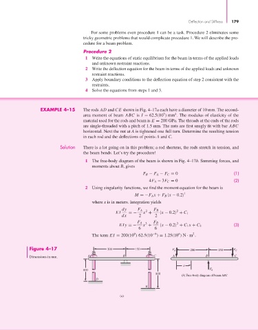
                            EXAMPLE 4–15       The rods AD and CE shown in Fig. 4–17a each have a diameter of 10 mm. The second-
                                                                                   3
                                                                                        4
                                               area moment of beam  ABC is  I = 62.5(10 ) mm . The modulus of elasticity of the
                                               material used for the rods and beam is E = 200 GPa. The threads at the ends of the rods
                                               are single-threaded with a pitch of 1.5 mm. The nuts are first snugly fit with bar ABC
                                               horizontal. Next the nut at A is tightened one full turn. Determine the resulting tension
                                               in each rod and the deflections of points A and C.
                                    Solution   There is a lot going on in this problem; a rod shortens, the rods stretch in tension, and
                                               the beam bends. Let’s try the procedure!
                                                1  The free-body diagram of the beam is shown in Fig. 4–17b. Summing forces, and
                                                   moments about B, gives
                                                                          F B − F A − F C = 0                     (1)
                                                                            4F A − 3F C = 0                       (2)
                                                2  Using singularity functions, we find the moment equation for the beam is
                                                                                            1
                                                                      M =−F A x + F B  x − 0.2
                                                   where x is in meters. Integration yields
                                                                dy     F A  2  F B       2
                                                             EI    =−     x +     x − 0.2  + C 1
                                                                dx      2      2
                                                                       F A  3  F B       3
                                                               EIy =−     x +     x − 0.2  + C 1 x + C 2          (3)
                                                                        6      6
                                                                                                2
                                                                              −9
                                                                                         4
                                                                     9
                                                   The term EI = 200(10 ) 62.5(10 ) = 1.25(10 ) N · m .
                       Figure 4–17                        200         150              F A     200         150    F C
                       Dimensions in mm.         A               B            C        A              B           C

                                                                                            x
                                                                                                       F
                                               600                                                      B
                                                                               800
                                                                                           (b) Free-body diagram of beam ABC
                                                     D
                                                                           E
                                                               (a)
   199   200   201   202   203   204   205   206   207   208   209