Page 207 - Shigley's Mechanical Engineering Design
P. 207

bud29281_ch04_147-211.qxd  11/27/09  2:55PM  Page 182 ntt 203:MHDQ196:bud29281:0073529281:bud29281_pagefiles:


                 182    Mechanical Engineering Design
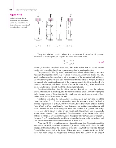
                  Figure 4–18                 P            P                  P
                                                                      P
                  (a) Both ends rounded or
                  pivoted; (b) both ends fixed;    y
                  (c) one end free and one end         l
                                                       4
                  fixed; (d) one end rounded and             A
                  pivoted, and one end fixed.                                 0.707l
                                                      l
                                           l                    l         l
                                                      2
                                                                               A
                                                            B
                                                       l
                                                       4

                                              x
                                                                      1
                                            (a) C   1  (b) C   4  (c) C     (d) C   2
                                                                      4

                                                                    2
                                              Using the relation  I = Ak , where  A is the area and  k the radius of gyration,
                                          enables us to rearrange Eq. (4–43) into the more convenient form
                                                                                2
                                                                       P cr  Cπ E
                                                                          =                                (4–44)
                                                                        A    (l/k) 2
                                          where l/k is called the  slenderness ratio. This ratio, rather than the actual column
                                          length, will be used in classifying columns according to length categories.
                                              The quantity P cr /A in Eq. (4–44) is the critical unit load. It is the load per unit area
                                          necessary to place the column in a condition of unstable equilibrium. In this state any
                                          small crookedness of the member, or slight movement of the support or load, will cause
                                          the column to begin to collapse. The unit load has the same units as strength, but this is
                                          the strength of a specific column, not of the column material. Doubling the length of a
                                          member, for example, will have a drastic effect on the value of P cr /A but no effect at
                                          all on, say, the yield strength S y of the column material itself.
                                              Equation (4–44) shows that the critical unit load depends only upon the end con-
                                          ditions, the modulus of elasticity, and the slenderness ratio. Thus a column obeying the
                                          Euler formula made of high-strength alloy steel is no stronger than one made of low-
                                          carbon steel, since E is the same for both.
                                              The factor C is called the end-condition constant, and it may have any one of the
                                                         1
                                          theoretical values  , 1, 2, and 4, depending upon the manner in which the load is
                                                         4
                                          applied. In practice it is difficult, if not impossible, to fix the column ends so that the
                                          factor C = 2 or C = 4 would apply. Even if the ends are welded, some deflection will
                                          occur. Because of this, some designers never use a value of  C greater than unity.
                                          However, if liberal factors of safety are employed, and if the column load is accurately
                                          known, then a value of C not exceeding 1.2 for both ends fixed, or for one end rounded
                                          and one end fixed, is not unreasonable, since it supposes only partial fixation. Of course,
                                                      1
                                          the value C =  must always be used for a column having one end fixed and one end
                                                      4
                                          free. These recommendations are summarized in Table 4–2.
                                              When Eq. (4–44) is solved for various values of the unit load P cr /A in terms of the
                                          slenderness ratio l/k, we obtain the curve PQR shown in Fig. 4–19. Since the yield
                                          strength of the material has the same units as the unit load, the horizontal line through
                                          S y and Q has been added to the figure. This would appear to make the figure S y QR
                                          cover the entire range of compression problems from the shortest to the longest
   202   203   204   205   206   207   208   209   210   211   212