
Page 210 - Shigley's Mechanical Engineering Design
P. 210
bud29281_ch04_147-211.qxd 11/27/09 2:55PM Page 185 ntt 203:MHDQ196:bud29281:0073529281:bud29281_pagefiles:
Deflection and Stiffness 185
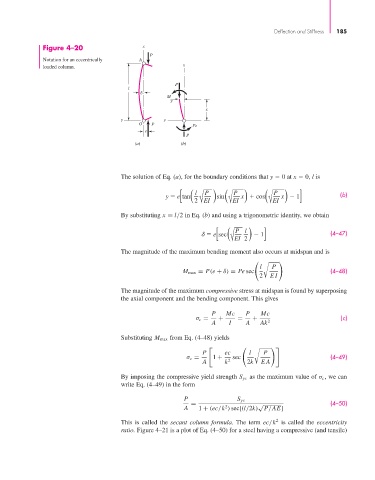
Figure 4–20 x
P
Notation for an eccentrically A
x
loaded column.
P
l
M
y
x
y y
O P Pe
e
P
(a) (b)
The solution of Eq. (a), for the boundary conditions that y 0 at x 0, l is
[ ( l ) ( ) ( ) ] (b)
P
P
P
y e tan 2 EI sin EI x cos EI x 1
By substituting x = l/2 in Eq. (b) and using a trigonometric identity, we obtain
[ ( ) ] (4–47)
lP
e sec
EI 2 1
The magnitude of the maximum bending moment also occurs at midspan and is
l P
M max = P(e + δ) = Pe sec (4–48)
2 EI
The magnitude of the maximum compressive stress at midspan is found by superposing
the axial component and the bending component. This gives
P Mc P Mc
σ c = + = + (c)
A I A Ak 2
Substituting M max from Eq. (4–48) yields
P ec l P
σ c = 1 + sec (4–49)
A k 2 2k EA
By imposing the compressive yield strength S yc as the maximum value of σ c , we can
write Eq. (4–49) in the form
P S yc
= √ (4–50)
2
A 1 + (ec/k ) sec[(l/2k) P/AE]
2
This is called the secant column formula. The term ec/k is called the eccentricity
ratio. Figure 4–21 is a plot of Eq. (4–50) for a steel having a compressive (and tensile)