
Page 214 - Shigley's Mechanical Engineering Design
P. 214
bud29281_ch04_147-211.qxd 11/27/09 2:55PM Page 189 ntt 203:MHDQ196:bud29281:0073529281:bud29281_pagefiles:
Deflection and Stiffness 189
of differentiating between a “secant column” and a strut, or short compression member,
is to say that in a strut, the effect of bending deflection must be limited to a certain small
percentage of the eccentricity. If we decide that the limiting percentage is to be 1 per-
cent of e, then, from Eq. (4–44), the limiting slenderness ratio turns out to be
1/2
l AE
= 0.282 (4–56)
k P
2
This equation then gives the limiting slenderness ratio for using Eq. (4–55). If the actual
slenderness ratio is greater than (l/k) 2 , then use the secant formula; otherwise, use
Eq. (4–55).
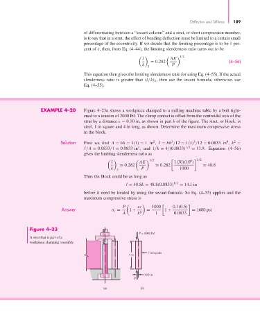
EXAMPLE 4–20 Figure 4–23a shows a workpiece clamped to a milling machine table by a bolt tight-
ened to a tension of 2000 lbf. The clamp contact is offset from the centroidal axis of the
strut by a distance e = 0.10 in, as shown in part b of the figure. The strut, or block, is
steel, 1 in square and 4 in long, as shown. Determine the maximum compressive stress
in the block.
Solution First we find A = bh = 1(1) = 1in , I = bh /12 = 1(1) /12 = 0.0833 in , k =
2
4
3
2
3
2
I/A = 0.0833/1 = 0.0833 in , and l/k = 4/(0.0833) 1/2 = 13.9. Equation (4–56)
gives the limiting slenderness ratio as
1/2 1/2
6
l AE 1(30)(10 )
= 0.282 = 0.282 = 48.8
k P 1000
2
Thus the block could be as long as
l = 48.8k = 48.8(0.0833) 1/2 = 14.1 in
before it need be treated by using the secant formula. So Eq. (4–55) applies and the
maximum compressive stress is
P ec 1000 0.1(0.5)
Answer σ c = 1 + = 1 + = 1600 psi
A k 2 1 0.0833
Figure 4–23
P = 1000 lbf
A strut that is part of a
workpiece clamping assembly.
1-in square
4 in
0.10 in
P
(a) (b)