
Page 213 - Shigley's Mechanical Engineering Design
P. 213
bud29281_ch04_147-211.qxd 12/9/09 8:51PM Page 188 ntt 203:MHDQ196:bud29281:0073529281:bud29281_pagefiles:
188 Mechanical Engineering Design
Solution (a) Using Eq. (4–44), we find the limiting slenderness ratio to be
l 2π CE 2π (1)(30)(10 )
2 1/2 2 6 1/2
= = = 88.9
k 75(10) 3
1 S y
By using P cr = n d P = 4(5000) = 20 000 lbf, Eqs. (4–52) and (4–54) are solved, using
3
5
various values of h, to form Table 4–3. The table shows that a cross section of by in,
8 4
which is marginally suitable, gives the least area.
(b) An approach similar to that in part (a) is used with l = 8 in. All trial computa-
tions are found to be in the J. B. Johnson region of l/k values. A minimum area occurs
1
when the section is a near square. Thus a cross section of by 3 in is found to be suit-
2 4
able and safe.
Table 4–3 h b A l/k Type Eq. No.
Table Generated to Solve 0.375 3.46 1.298 139 Euler (4–52)
Ex. 4–19, part (a) 0.500 1.46 0.730 104 Euler (4–52)
0.625 0.76 0.475 83 Johnson (4–54)
0.5625 1.03 0.579 92 Euler (4–52)
4–15 Struts or Short Compression Members
A short bar loaded in pure compression by a force P acting along the centroidal axis
will shorten in accordance with Hooke’s law, until the stress reaches the elastic limit of
the material. At this point, permanent set is introduced and usefulness as a machine
member may be at an end. If the force P is increased still more, the material either
becomes “barrel-like” or fractures. When there is eccentricity in the loading, the elastic
limit is encountered at smaller loads.
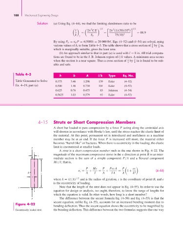
P
A strut is a short compression member such as the one shown in Fig. 4–22. The
x
e magnitude of the maximum compressive stress in the x direction at point B in an inter-
mediate section is the sum of a simple component P/A and a flexural component
Mc/I; that is,
P Mc P PecA P ec
σ c = + = + = 1 + (4–55)
B l A I A IA A k 2
c
where k = (I/A) 1/2 and is the radius of gyration, c is the coordinate of point B, and e
is the eccentricity of loading.
y Note that the length of the strut does not appear in Eq. (4–55). In order to use the
equation for design or analysis, we ought, therefore, to know the range of lengths for
which the equation is valid. In other words, how long is a short member?
P The difference between the secant formula Eq. (4–50) and Eq. (4–55) is that the
secant equation, unlike Eq. (4–55), accounts for an increased bending moment due to
Figure 4–22
bending deflection. Thus the secant equation shows the eccentricity to be magnified by
Eccentrically loaded strut. the bending deflection. This difference between the two formulas suggests that one way