Page 218 - Shigley's Mechanical Engineering Design
P. 218

bud29281_ch04_147-211.qxd  11/27/09  2:55PM  Page 193 ntt 203:MHDQ196:bud29281:0073529281:bud29281_pagefiles:


                                                                                              Deflection and Stiffness  193


                                                   O                       F
                                                         L              B
                                   Problem 4–1
                                                                 A    l
                                                                          y

                                                                  R


                                       4–2     For Prob. 4–1, if the simple support at point A were eliminated and the cantilever spring rate
                                               of OA is given by k L , determine the overall spring rate of the bar based on the deflection of
                                               point B.
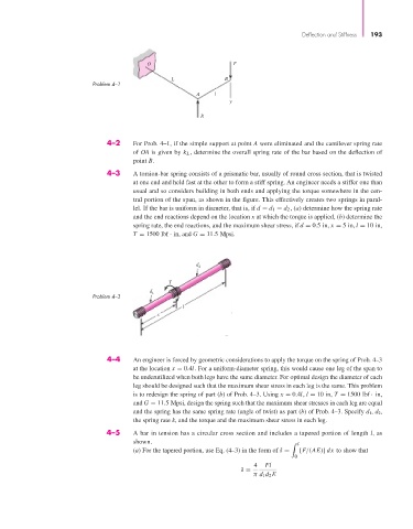
                                       4–3     A torsion-bar spring consists of a prismatic bar, usually of round cross section, that is twisted
                                               at one end and held fast at the other to form a stiff spring. An engineer needs a stiffer one than
                                               usual and so considers building in both ends and applying the torque somewhere in the cen-
                                               tral portion of the span, as shown in the figure. This effectively creates two springs in paral-
                                               lel. If the bar is uniform in diameter, that is, if d = d 1 = d 2 , (a) determine how the spring rate
                                               and the end reactions depend on the location x at which the torque is applied, (b) determine the
                                               spring rate, the end reactions, and the maximum shear stress, if d = 0.5 in, x = 5 in, l = 10 in,
                                               T = 1500 lbf · in, and G = 11.5 Mpsi.


                                                                d
                                                                 2
                                                         T
                                                   d
                                   Problem 4–3      1
                                                             l
                                                      x


                                       4–4     An engineer is forced by geometric considerations to apply the torque on the spring of Prob. 4–3
                                               at the location x = 0.4l. For a uniform-diameter spring, this would cause one leg of the span to
                                               be underutilized when both legs have the same diameter. For optimal design the diameter of each
                                               leg should be designed such that the maximum shear stress in each leg is the same. This problem
                                               is to redesign the spring of part (b) of Prob. 4–3. Using x = 0.4l, l = 10 in, T = 1500 lbf · in,
                                               and G = 11.5 Mpsi, design the spring such that the maximum shear stresses in each leg are equal
                                               and the spring has the same spring rate (angle of twist) as part (b) of Prob. 4–3. Specify d 1, d 2,
                                               the spring rate k, and the torque and the maximum shear stress in each leg.
                                       4–5     A bar in tension has a circular cross section and includes a tapered portion of length l, as
                                               shown.                                         l
                                               (a) For the tapered portion, use Eq. (4–3) in the form of δ =  [F/(AE)] dx to show that
                                                                                            0
                                                                                 4  Fl
                                                                             δ =
                                                                                π d 1 d 2 E
   213   214   215   216   217   218   219   220   221   222   223