
Page 220 - Shigley's Mechanical Engineering Design
P. 220
bud29281_ch04_147-211.qxd 11/27/09 2:55PM Page 195 ntt 203:MHDQ196:bud29281:0073529281:bud29281_pagefiles:
Deflection and Stiffness 195
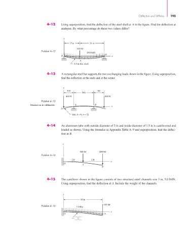
4–12 Using superposition, find the deflection of the steel shaft at A in the figure. Find the deflection at
midspan. By what percentage do these two values differ?
y
15 in 24 in
340 lbf
Problem 4–12
150 lbf/ft
B
O x
A
1.5 in-dia. shaft
4–13 A rectangular steel bar supports the two overhanging loads shown in the figure. Using superposition,
find the deflection at the ends and at the center.
y
300 300
500
400 N 400 N
Problem 4–13
Dimensions in millimeters. A B
x
O C
Bar, b = 6, h = 32
4–14 An aluminum tube with outside diameter of 2 in and inside diameter of 1.5 in is cantilevered and
loaded as shown. Using the formulas in Appendix Table A–9 and superposition, find the deflec-
tion at B.
y
300 lbf 200 lbf
Problem 4–14
2 ft 2 ft
x
O
A
B
4–15 The cantilever shown in the figure consists of two structural-steel channels size 3 in, 5.0 lbf/ft.
Using superposition, find the deflection at A. Include the weight of the channels.
y
60 in
150 lbf
Problem 4–15 5 lbf/in
x
O A