
Page 224 - Shigley's Mechanical Engineering Design
P. 224
bud29281_ch04_147-211.qxd 12/9/09 8:51PM Page 199 ntt 203:MHDQ196:bud29281:0073529281:bud29281_pagefiles:
Deflection and Stiffness 199
y
2 in
A C
1-in dia.
1 in F y 3 -in dia.
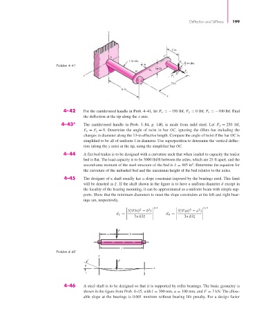
Problem 4–41 4 1 4
1 in
2
B F x
z F z D
5 in
6 in
x
4–42 For the cantilevered handle in Prob. 4–41, let F x =−150 lbf, F y = 0 lbf, F z =−100 lbf. Find
the deflection at the tip along the x axis.
4–43* The cantilevered handle in Prob. 3–84, p. 140, is made from mild steel. Let F y = 250 lbf,
F x = F z = 0. Determine the angle of twist in bar OC, ignoring the fillets but including the
changes in diameter along the 13-in effective length. Compare the angle of twist if the bar OC is
simplified to be all of uniform 1-in diameter. Use superposition to determine the vertical deflec-
tion (along the y axis) at the tip, using the simplified bar OC.
4–44 A flat-bed trailer is to be designed with a curvature such that when loaded to capacity the trailer
bed is flat. The load capacity is to be 3000 lbf/ft between the axles, which are 25 ft apart, and the
4
second-area moment of the steel structure of the bed is I = 485 in . Determine the equation for
the curvature of the unloaded bed and the maximum height of the bed relative to the axles.
4–45 The designer of a shaft usually has a slope constraint imposed by the bearings used. This limit
will be denoted as ξ. If the shaft shown in the figure is to have a uniform diameter d except in
the locality of the bearing mounting, it can be approximated as a uniform beam with simple sup-
ports. Show that the minimum diameters to meet the slope constraints at the left and right bear-
ings are, respectively,
1/4 1/4
2 2
2 2
32Fb(l − b ) 32Fa(l − a )
3π Elξ d R = 3π Elξ
d L =
F
a b
l
Problem 4–45
y
F
x
4–46 A steel shaft is to be designed so that it is supported by roller bearings. The basic geometry is
shown in the figure from Prob. 4–45, with l = 300 mm, a = 100 mm, and F = 3 kN. The allow-
able slope at the bearings is 0.001 mm/mm without bearing life penalty. For a design factor