
Page 225 - Shigley's Mechanical Engineering Design
P. 225
bud29281_ch04_147-211.qxd 11/27/09 2:55PM Page 200 ntt 203:MHDQ196:bud29281:0073529281:bud29281_pagefiles:
200 Mechanical Engineering Design
of 1.28, what uniform-diameter shaft will support the load without penalty? Determine the
maximum deflection of the shaft.
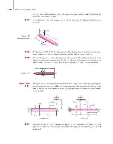
4–47 If the diameter of the steel beam shown is 1.25 in, determine the deflection of the beam at
x = 8 in.
y
150 lbf
5
A
Problem 4–47
15
Dimensions in inches. z
10
B
250 lbf
x
4–48 For the beam of Prob. 4–47, plot the magnitude of the displacement of the beam in 0.1-in incre-
ments. Approximate the maximum displacement and the value of x where it occurs.
4–49 Shown in the figure is a uniform-diameter shaft with bearing shoulders at the ends; the shaft is sub-
jected to a concentrated moment M = 1000 lbf · in. The shaft is of carbon steel and has a = 4 in
and l = 10 in. The slope at the ends must be limited to 0.002 rad. Find a suitable diameter d.
a b
M B
Problem 4–49
B
l
4–50* and The figure shows a rectangular member OB, made from -in-thick aluminum plate, pinned to the
1
4
1
4–51 ground at one end and supported by a -in-diameter round steel rod with hooks formed on the
2
ends. A load of 100 lbf is applied as shown. Use superposition to determine the vertical deflec-
tion at point B.
C C 100 lbf
1 -in dia. 1 -in dia.
2 2
100 lbf
1 -in thick 12 in 12 in 1 -in thick
2 in 4 2 in 4
A A D
O B O 7 in B
6 in 12 in 6 in 12 in
Problem 4–50* Problem 4–51
4–52 The figure illustrates a stepped torsion-bar spring OA with an actuating cantilever AB. Both
parts are of carbon steel. Use superposition and find the spring rate k corresponding to a force F
acting at B.