Page 222 - Shigley's Mechanical Engineering Design
P. 222

bud29281_ch04_147-211.qxd  11/27/09  2:55PM  Page 197 ntt 203:MHDQ196:bud29281:0073529281:bud29281_pagefiles:


                                                                                              Deflection and Stiffness  197
                                      4–20     Like Prob. 4–18, this problem provides another beam to add to Table A–9. For the simply sup-
                                               ported beam shown with an overhanging uniform load, use statics and double integration to
                                               show that
                                                           wa 2        wa                  wa 2
                                                       R 1 =       R 2 =  (2l + a)  V AB =−        V BC = w(l + a − x)
                                                            2l          2l                  2l
                                                            wa 2            w         2
                                                     M AB =−    x    M BC =−  (l + a − x)
                                                             2l              2
                                                              2
                                                           wa x  2   2             w           4    2             4
                                                      y AB =    (l − x )   y BC =−    [(l + a − x) − 4a (l − x)(l + a) − a ]
                                                           12EIl                  24EI


                                                y
                                                        l           a
                                                 R                  w
                                   Problem 4–20  1
                                               A               B         C
                                                                            x
                                                                 R 2


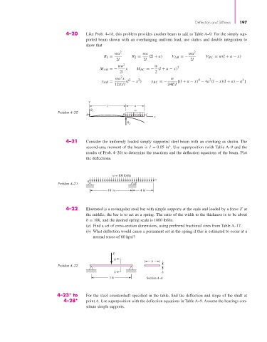
                                      4–21     Consider the uniformly loaded simply supported steel beam with an overhang as shown. The
                                                                                   4
                                               second-area moment of the beam is  I = 0.05 in . Use superposition (with Table A–9 and the
                                               results of Prob. 4–20) to determine the reactions and the deflection equations of the beam. Plot
                                               the deflections.


                                                          w = 100 lbf/in
                                                                            C
                                               A
                                   Problem 4–21                     B
                                                y                  y
                                                        10 in         4 in


                                      4–22     Illustrated is a rectangular steel bar with simple supports at the ends and loaded by a force F at
                                               the middle; the bar is to act as a spring. The ratio of the width to the thickness is to be about
                                               b = 10h, and the desired spring scale is 1800 lbf/in.
                                               (a) Find a set of cross-section dimensions, using preferred fractional sizes from Table A–17.
                                               (b) What deflection would cause a permanent set in the spring if this is estimated to occur at a
                                                  normal stress of 60 kpsi?


                                                          F
                                                           A
                                                                           b
                                   Problem 4–22
                                                           A                    h
                                                         3 ft            Section A–A


                                  4–23* to     For the steel countershaft specified in the table, find the deflection and slope of the shaft at
                                     4–28*     point A. Use superposition with the deflection equations in Table A–9. Assume the bearings con-
                                               stitute simple supports.
   217   218   219   220   221   222   223   224   225   226   227