
Page 219 - Shigley's Mechanical Engineering Design
P. 219
bud29281_ch04_147-211.qxd 11/27/2009 7:54 pm Page 194 pinnacle s-171:Desktop Folder:Temp Work:Don't Delete (Jobs):MHDQ196/Budynas:
194 Mechanical Engineering Design
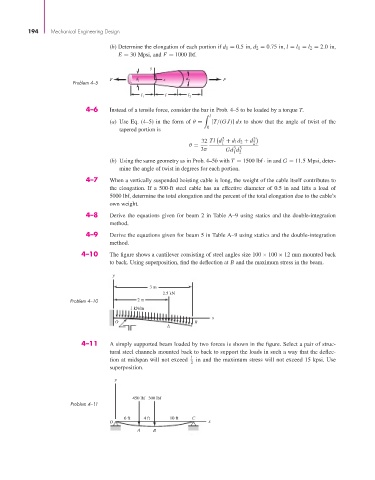
(b) Determine the elongation of each portion if d 1 = 0.5 in, d 2 = 0.75 in, l = l 1 = l 2 = 2.0 in,
E = 30 Mpsi, and F = 1000 lbf.
y
F d l x d 2 F
Problem 4–5
l l l
1 2
4–6 Instead of a tensile force, consider the bar in Prob. 4–5 to be loaded by a torque T.
l
(a) Use Eq. (4–5) in the form of θ = [T/(GJ)] dx to show that the angle of twist of the
0
tapered portion is
2 2
32 Tl d + d 1 d 2 + d 2
1
θ =
3 3
3π Gd d
1 2
(b) Using the same geometry as in Prob. 4–5b with T = 1500 lbf · in and G = 11.5 Mpsi, deter-
mine the angle of twist in degrees for each portion.
4–7 When a vertically suspended hoisting cable is long, the weight of the cable itself contributes to
the elongation. If a 500-ft steel cable has an effective diameter of 0.5 in and lifts a load of
5000 lbf, determine the total elongation and the percent of the total elongation due to the cable’s
own weight.
4–8 Derive the equations given for beam 2 in Table A–9 using statics and the double-integration
method.
4–9 Derive the equations given for beam 5 in Table A–9 using statics and the double-integration
method.
4–10 The figure shows a cantilever consisting of steel angles size 100 × 100 × 12 mm mounted back
to back. Using superposition, find the deflection at B and the maximum stress in the beam.
y
3 m
2.5 kN
Problem 4–10 2 m
1 kN/m
x
O B
A
4–11 A simply supported beam loaded by two forces is shown in the figure. Select a pair of struc-
tural steel channels mounted back to back to support the loads in such a way that the deflec-
1
tion at midspan will not exceed in and the maximum stress will not exceed 15 kpsi. Use
2
superposition.
y
450 lbf 300 lbf
Problem 4–11
6 ft 4 ft 10 ft C
O x
A B