
Page 216 - Shigley's Mechanical Engineering Design
P. 216
bud29281_ch04_147-211.qxd 11/27/09 2:55PM Page 191 ntt 203:MHDQ196:bud29281:0073529281:bud29281_pagefiles:
Deflection and Stiffness 191
4–17 Shock and Impact
Impact refers to the collision of two masses with initial relative velocity. In some cases
it is desirable to achieve a known impact in design; for example, this is the case in the
design of coining, stamping, and forming presses. In other cases, impact occurs because
of excessive deflections, or because of clearances between parts, and in these cases it is
desirable to minimize the effects. The rattling of mating gear teeth in their tooth spaces
is an impact problem caused by shaft deflection and the clearance between the teeth.
This impact causes gear noise and fatigue failure of the tooth surfaces. The clearance
space between a cam and follower or between a journal and its bearing may result in
crossover impact and also cause excessive noise and rapid fatigue failure.
Shock is a more general term that is used to describe any suddenly applied force or
disturbance. Thus the study of shock includes impact as a special case.
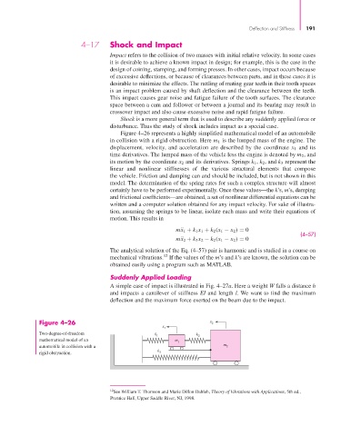
Figure 4–26 represents a highly simplified mathematical model of an automobile
in collision with a rigid obstruction. Here m 1 is the lumped mass of the engine. The
displacement, velocity, and acceleration are described by the coordinate x 1 and its
time derivatives. The lumped mass of the vehicle less the engine is denoted by m 2 , and
its motion by the coordinate x 2 and its derivatives. Springs k 1 , k 2 , and k 3 represent the
linear and nonlinear stiffnesses of the various structural elements that compose
the vehicle. Friction and damping can and should be included, but is not shown in this
model. The determination of the spring rates for such a complex structure will almost
certainly have to be performed experimentally. Once these values—the k’s, m’s, damping
and frictional coefficients—are obtained, a set of nonlinear differential equations can be
written and a computer solution obtained for any impact velocity. For sake of illustra-
tion, assuming the springs to be linear, isolate each mass and write their equations of
motion. This results in
x
m ¨ 1 + k 1 x 1 + k 2 (x 1 − x 2 ) = 0
(4–57)
x
m ¨ 2 + k 3 x 2 − k 2 (x 1 − x 2 ) = 0
The analytical solution of the Eq. (4–57) pair is harmonic and is studied in a course on
12
mechanical vibrations. If the values of the m’s and k’s are known, the solution can be
obtained easily using a program such as MATLAB.
Suddenly Applied Loading
A simple case of impact is illustrated in Fig. 4–27a. Here a weight W falls a distance h
and impacts a cantilever of stiffness EI and length l. We want to find the maximum
deflection and the maximum force exerted on the beam due to the impact.
Figure 4–26 x 2
x
1
Two-degree-of-freedom k k
1 2
mathematical model of an m 1
automobile in collision with a m 2
k
rigid obstruction. 3
12 See William T. Thomson and Marie Dillon Dahleh, Theory of Vibrations with Applications, 5th ed.,
Prentice Hall, Upper Saddle River, NJ, 1998.