
Page 221 - Shigley's Mechanical Engineering Design
P. 221
bud29281_ch04_147-211.qxd 12/9/09 8:51PM Page 196 ntt 203:MHDQ196:bud29281:0073529281:bud29281_pagefiles:
196 Mechanical Engineering Design
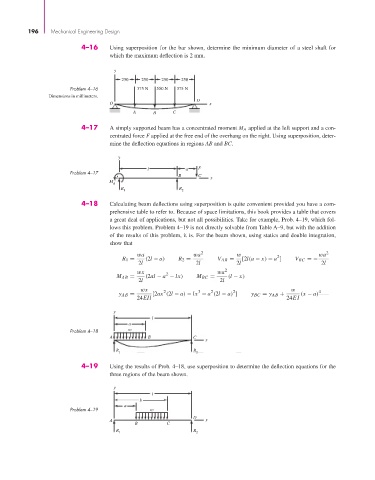
4–16 Using superposition for the bar shown, determine the minimum diameter of a steel shaft for
which the maximum deflection is 2 mm.
y
250 250 250 250
Problem 4–16 375 N 550 N 375 N
Dimensions in millimeters.
D
O x
A B C
4–17 A simply supported beam has a concentrated moment M A applied at the left support and a con-
centrated force F applied at the free end of the overhang on the right. Using superposition, deter-
mine the deflection equations in regions AB and BC.
y
l a F
Problem 4–17
A B C x
M A
R R
1 2
4–18 Calculating beam deflections using superposition is quite convenient provided you have a com-
prehensive table to refer to. Because of space limitations, this book provides a table that covers
a great deal of applications, but not all possibilities. Take for example, Prob. 4–19, which fol-
lows this problem. Problem 4–19 is not directly solvable from Table A–9, but with the addition
of the results of this problem, it is. For the beam shown, using statics and double integration,
show that
wa wa 2 w 2 wa 2
R 1 = (2l − a) R 2 = V AB = [2l(a − x) − a ] V BC =−
2l 2l 2l 2l
wx 2 wa 2
M AB = (2al − a − lx) M BC = (l − x)
2l 2l
wx 2 3 2 2 w 4
y AB = [2ax (2l − a) − lx − a (2l − a) ] y BC = y AB + (x − a)
24EIl 24EI
y
l
a
Problem 4–18 w
A B C
x
R 1 R 2
4–19 Using the results of Prob. 4–18, use superposition to determine the deflection equations for the
three regions of the beam shown.
y
l
b
a
Problem 4–19 w
D
A x
B C
R
R 1 2