
Page 199 - Shigley's Mechanical Engineering Design
P. 199
bud29281_ch04_147-211.qxd 11/27/09 2:55PM Page 174 ntt 203:MHDQ196:bud29281:0073529281:bud29281_pagefiles:
174 Mechanical Engineering Design
Figure 4–14
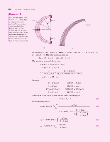
(a) A steel punch press has a
C frame with a varying-depth
32-in R 1000 lbf
rectangular cross section
depicted. The cross section
1000 lbf
varies sinusoidally from
◦
2in × 2 in at θ = 0 to
◦
2in × 6 in at θ = 90 , and
◦
back to 2in × 2 in at θ = 180 .
Of immediate interest to the
designer is the deflection in the
load axis direction under the 1000 lbf
load. (b) Finite-element model.
(a) (b)
6
an amplitude of 2 in. The load is 1000 lbf. It follows that C = 1.2, G = 11.5(10 ) psi,
6
E = 30(10 ) psi. The outer and inner radii are
R out = 33 + 2 sin θ R in = 31 − 2 sin θ
The remaining geometrical terms are
h = R out − R in = 2(1 + 2 sin θ) -
A = bh = 4(1 + 2 sin θ)
h 2(1 + 2 sin θ)
r n = = 1
ln(R out /R in ) ln[(33 + 2 sin θ)/(31 − 2 sin θ)]
e = R − r n = 32 − r n
Note that
M = FR sin θ ∂M/∂F = R sin θ
F θ = F sin θ ∂F θ /∂F = sin θ
2
2
2
MF θ = F R sin θ ∂MF θ /∂F = 2FR sin θ
F r = F cos θ ∂F r /∂F = cos θ
Substitution of the terms into Eq. (4–38) yields three integrals
(1)
δ = I 1 + I 2 + I 3
where the integrals are
2
π sin θ dθ
−3
I 1 = 8.5333(10 ) ⎡ ⎤ (2)
0
2(1 + 2 sin θ)
⎢ ⎥
(1 + 2 sin θ) 32 − ⎥
⎢
⎣ 33 + 2 sin θ ⎦
ln
31 − 2 sin θ
2
π sin θ dθ
−4
I 2 =−2.6667(10 ) (3)
0 1 + 2 sin θ
2
π cos θ dθ
−4
I 3 = 8.3478(10 ) (4)
0 1 + 2 sin θ