
Page 195 - Shigley's Mechanical Engineering Design
P. 195
bud29281_ch04_147-211.qxd 11/27/09 2:55PM Page 170 ntt 203:MHDQ196:bud29281:0073529281:bud29281_pagefiles:
170 Mechanical Engineering Design
F
d r
M
F
h
R
F
F
(a) (b)
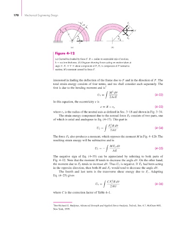
Figure 4–12
(a) Curved bar loaded by force F. R = radius to centroidal axis of section;
h = section thickness. (b) Diagram showing forces acting on section taken at
angle θ. F r = V = shear component of F; F θ is component of F normal to
section; M is moment caused by force F.
interested in finding the deflection of the frame due to F and in the direction of F. The
total strain energy consists of four terms, and we shall consider each separately. The
first is due to the bending moment and is 7
M dθ
2
U 1 = (4–32)
2AeE
In this equation, the eccentricity e is
(4–33)
e = R − r n
where r n is the radius of the neutral axis as defined in Sec. 3–18 and shown in Fig. 3–34.
The strain energy component due to the normal force F θ consists of two parts, one
of which is axial and analogous to Eq. (4–17). This part is
F Rdθ
2
θ
U 2 = (4–34)
2AE
The force F θ also produces a moment, which opposes the moment M in Fig. 4–12b. The
resulting strain energy will be subtractive and is
MF θ dθ
U 3 =− (4–35)
AE
The negative sign of Eq. (4–35) can be appreciated by referring to both parts of
Fig. 4–12. Note that the moment M tends to decrease the angle dθ. On the other hand,
the moment due to F θ tends to increase dθ. Thus U 3 is negative. If F θ had been acting
in the opposite direction, then both M and F θ would tend to decrease the angle dθ.
The fourth and last term is the transverse shear energy due to F r . Adapting
Eq. (4–25) gives
CF Rdθ
2
r
U 4 = (4–36)
2AG
where C is the correction factor of Table 4–1.
7 See Richard G. Budynas, Advanced Strength and Applied Stress Analysis, 2nd ed., Sec. 6.7, McGraw-Hill,
New York, 1999.