
Page 192 - Shigley's Mechanical Engineering Design
P. 192
bud29281_ch04_147-211.qxd 11/27/09 2:55PM Page 167 ntt 203:MHDQ196:bud29281:0073529281:bud29281_pagefiles:
Deflection and Stiffness 167
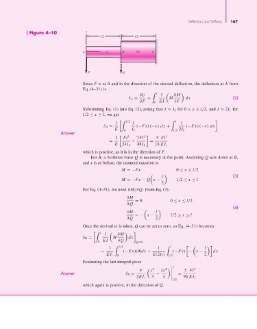
Figure 4–10 y
l/2 l/2
A x I 1 B 2I 1 C
F Q
Since F is at A and in the direction of the desired deflection, the deflection at A from
Eq. (4–31) is
∂U l 1 ∂M
δ A = = M dx (2)
∂F 0 EI ∂F
Substituting Eq. (1) into Eq. (2), noting that I = I 1 for 0 ≤ x ≤ l/2, and I = 2I 1 for
l/2 ≤ x ≤ l, we get
1 l/2 1 l 1
δ A = (−Fx) (−x) dx + (−Fx) (−x) dx
E 0 I 1 l/2 2I 1
Answer
1 Fl 3 7Fl 3 3 Fl 3
= + =
E 24I 1 48I 1 16 EI 1
which is positive, as it is in the direction of F.
For B, a fictitious force Q is necessary at the point. Assuming Q acts down at B,
and x is as before, the moment equation is
M =−Fx 0 ≤ x ≤ l/2
(3)
l
M =−Fx − Q x − l/2 ≤ x ≤ l
2
For Eq. (4–31), we need ∂M/∂Q. From Eq. (3),
∂M
= 0 0 ≤ x ≤ l/2
∂Q
(4)
∂M l
=− x − l/2 ≤ x ≤ l
∂Q 2
Once the derivative is taken, Q can be set to zero, so Eq. (4–31) becomes
l
1 ∂M
δ B = M dx
0 EI ∂Q Q=0
1 l/2 1 l l
= (−Fx)(0)dx + (−Fx) − x − dx
EI 1 0 E(2I 1 ) l/2 2
Evaluating the last integral gives
l 3
2
3
F x lx 5 Fl
Answer δ B = − =
2EI 1 3 4 96 EI 1
l/2
which again is positive, in the direction of Q.