
Page 197 - Shigley's Mechanical Engineering Design
P. 197
bud29281_ch04_147-211.qxd 11/27/2009 7:54 pm Page 172 pinnacle s-171:Desktop Folder:Temp Work:Don't Delete (Jobs):MHDQ196/Budynas:
172 Mechanical Engineering Design
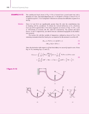
EXAMPLE 4–12 The cantilevered hook shown in Fig. 4–13a is formed from a round steel wire with a
diameter of 2 mm. The hook dimensions are l = 40 and R = 50 mm. A force P of 1 N
is applied at point C. Use Castigliano’s theorem to estimate the deflection at point D at
the tip.
Solution Since l/d and R/d are significantly greater than 10, only the contributions due
to bending will be considered. To obtain the vertical deflection at D, a fictitious
force Q will be applied there. Free-body diagrams are shown in Figs. 4–13b, c, and
d, with breaks in sections AB, BC, and CD, respectively. The normal and shear
forces, N and V respectively, are shown but are considered negligible in the deflec-
tion analysis.
For section AB, with the variable of integration x defined as shown in Fig. 4–13b,
summing moments about the break gives an equation for the moment in section AB,
M AB = P(R + x) + Q(2R + x) (1)
∂M AB /∂Q = 2R + x (2)
Since the derivative with respect to Q has been taken, we can set Q equal to zero. From
Eq. (4–31), inserting Eqs. (1) and (2),
l l
1 ∂M AB 1
(δ D ) AB = M AB dx = P(R + x)(2R + x)dx
0 EI ∂Q EI 0
(3)
P l 2 2 P 2 3 2 1 3
= (2R + 3Rx + x )dx = (2R l + l R + l )
EI 0 EI 2 3
Figure 4–13 l
D
A B
R
P
C
(a)
Q Q Q
V AB x
D D D
B R R
M V
AB N BC
P BC P V CD
M
BC M
N CD CD
C C
(b) (c) (d)