
Page 246 - Shigley's Mechanical Engineering Design
P. 246
bud29281_ch05_212-264.qxd 11/27/2009 6:46 pm Page 221 pinnacle s-171:Desktop Folder:Temp Work:Don't Delete (Jobs):MHDQ196/Budynas:
Failures Resulting from Static Loading 221
Figure 5–7 B
S Case 1
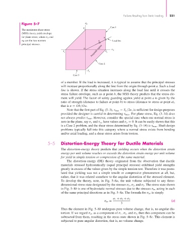
The maximum-shear-stress y
(MSS) theory yield envelope
for plane stress, where σ A and b
σ B are the two nonzero a Load line
principal stresses.
Nonyield region S A
O
–S y y
Case 2
–S
y
Case 3
of a member. If the load is increased, it is typical to assume that the principal stresses
will increase proportionally along the line from the origin through point a. Such a load
line is shown. If the stress situation increases along the load line until it crosses the
stress failure envelope, such as at point b, the MSS theory predicts that the stress ele-
ment will yield. The factor of safety guarding against yield at point a is given by the
ratio of strength (distance to failure at point b) to stress (distance to stress at point a),
that is n = Ob/Oa.
Note that the first part of Eq. (5–3), τ max = S y /2n, is sufficient for design purposes
provided the designer is careful in determining τ max . For plane stress, Eq. (3–14) does
not always predict τ max . However, consider the special case when one normal stress is
zero in the plane, say σ x and τ xy have values and σ y = 0. It can be easily shown that this
is a Case 2 problem, and the shear stress determined by Eq. (3–14) is τ max . Shaft design
problems typically fall into this category where a normal stress exists from bending
and/or axial loading, and a shear stress arises from torsion.
5–5 Distortion-Energy Theory for Ductile Materials
The distortion-energy theory predicts that yielding occurs when the distortion strain
energy per unit volume reaches or exceeds the distortion strain energy per unit volume
for yield in simple tension or compression of the same material.
The distortion-energy (DE) theory originated from the observation that ductile
materials stressed hydrostatically (equal principal stresses) exhibited yield strengths
greatly in excess of the values given by the simple tension test. Therefore it was postu-
lated that yielding was not a simple tensile or compressive phenomenon at all, but,
rather, that it was related somehow to the angular distortion of the stressed element.
To develop the theory, note, in Fig. 5–8a, the unit volume subjected to any three-
dimensional stress state designated by the stresses σ 1 , σ 2 , and σ 3 . The stress state shown
in Fig. 5–8b is one of hydrostatic normal stresses due to the stresses σ av acting in each
of the same principal directions as in Fig. 5–8a. The formula for σ av is simply
σ 1 + σ 2 + σ 3
σ av = (a)
3
Thus the element in Fig. 5–8b undergoes pure volume change, that is, no angular dis-
tortion. If we regard σ av as a component of σ 1 , σ 2 , and σ 3 , then this component can be
subtracted from them, resulting in the stress state shown in Fig. 5–8c. This element is
subjected to pure angular distortion, that is, no volume change.