
Page 292 - Shigley's Mechanical Engineering Design
P. 292
bud29281_ch06_265-357.qxd 12/9/09 7:17PM Page 267 ntt 203:MHDQ196:bud29281:0073529281:bud29281_pagefiles:
Fatigue Failure Resulting from Variable Loading 267
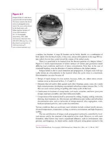
Figure 6–1
Fatigue failure of a bolt due to
repeated unidirectional bending.
The failure started at the thread
root at A, propagated across
most of the cross section shown
by the beach marks at B,
before final fast fracture at C.
(From ASM Handbook,
Vol. 12: Fractography,
2nd printing, 1992, ASM
International, Materials Park,
OH 44073-0002, fig 50, p. 120.
Reprinted by permission of
®
ASM International ,
www.asminternational.org.)
a sudden, fast fracture. A stage III fracture can be brittle, ductile, or a combination of
both. Quite often the beach marks, if they exist, and possible patterns in the stage III frac-
ture called chevron lines, point toward the origins of the initial cracks.
There is a good deal to be learned from the fracture patterns of a fatigue failure. 1
Figure 6–2 shows representations of failure surfaces of various part geometries under
differing load conditions and levels of stress concentration. Note that, in the case of
rotational bending, even the direction of rotation influences the failure pattern.
Fatigue failure is due to crack formation and propagation. A fatigue crack will typ-
ically initiate at a discontinuity in the material where the cyclic stress is a maximum.
Discontinuities can arise because of:
• Design of rapid changes in cross section, keyways, holes, etc. where stress concen-
trations occur as discussed in Secs. 3–13 and 5–2.
• Elements that roll and/or slide against each other (bearings, gears, cams, etc.) under
high contact pressure, developing concentrated subsurface contact stresses (Sec. 3–19)
that can cause surface pitting or spalling after many cycles of the load.
• Carelessness in locations of stamp marks, tool marks, scratches, and burrs; poor joint
design; improper assembly; and other fabrication faults.
• Composition of the material itself as processed by rolling, forging, casting, extrusion,
drawing, heat treatment, etc. Microscopic and submicroscopic surface and subsurface
discontinuities arise, such as inclusions of foreign material, alloy segregation, voids,
hard precipitated particles, and crystal discontinuities.
Various conditions that can accelerate crack initiation include residual tensile stresses,
elevated temperatures, temperature cycling, a corrosive environment, and high-frequency
cycling.
The rate and direction of fatigue crack propagation is primarily controlled by local-
ized stresses and by the structure of the material at the crack. However, as with crack
formation, other factors may exert a significant influence, such as environment, tem-
perature, and frequency. As stated earlier, cracks will grow along planes normal to the
1 See the ASM Handbook, Fractography, ASM International, Metals Park, Ohio, vol. 12, 9th ed., 1987.