
Page 294 - Shigley's Mechanical Engineering Design
P. 294
bud29281_ch06_265-357.qxd 12/02/2009 6:49 pm Page 269 pinnacle s-171:Desktop Folder:Temp Work:Don't Delete (Jobs):MHDQ196/Budynas:
Fatigue Failure Resulting from Variable Loading 269
maximum tensile stresses. The crack growth process can be explained by fracture
mechanics (see Sec. 6–6).
A major reference source in the study of fatigue failure is the 21-volume
ASM Metals Handbook. Figures 6–1 to 6–8, reproduced with permission from ASM
International, are but a minuscule sample of examples of fatigue failures for a great
variety of conditions included in the handbook. Comparing Fig. 6–3 with Fig. 6–2, we
see that failure occurred by rotating bending stresses, with the direction of rotation
being clockwise with respect to the view and with a mild stress concentration and low
nominal stress.
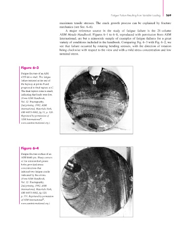
Figure 6–3
Fatigue fracture of an AISI
4320 drive shaft. The fatigue
failure initiated at the end of
the keyway at points B and
progressed to final rupture at C.
The final rupture zone is small,
indicating that loads were low.
(From ASM Handbook,
Vol. 12: Fractography,
2nd printing, 1992, ASM
International, Materials Park,
OH 44073-0002, fig 51, p. 120.
Reprinted by permission of
®
ASM International ,
www.asminternational.org.)
Figure 6–4
Fatigue fracture surface of an
AISI 8640 pin. Sharp corners
of the mismatched grease
holes provided stress
concentrations that
initiated two fatigue cracks
indicated by the arrows.
(From ASM Handbook,
Vol. 12: Fractography,
2nd printing, 1992, ASM
International, Materials Park,
OH 44073-0002, fig 520,
p. 331. Reprinted by permission
®
of ASM International ,
www.asminternational.org.)