
Page 295 - Shigley's Mechanical Engineering Design
P. 295
bud29281_ch06_265-357.qxd 12/02/2009 6:49 pm Page 270 pinnacle s-171:Desktop Folder:Temp Work:Don't Delete (Jobs):MHDQ196/Budynas:
270 Mechanical Engineering Design
Figure 6–5
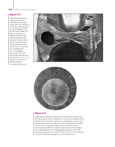
Fatigue fracture surface of a
forged connecting rod of
AISI 8640 steel. The fatigue
crack origin is at the left edge, at
the flash line of the forging, but
no unusual roughness of the
flash trim was indicated. The
fatigue crack progressed
halfway around the oil hole
at the left, indicated by the
beach marks, before final fast
fracture occurred. Note the
pronounced shear lip in the
final fracture at the right edge.
(From ASM Handbook,
Vol. 12: Fractography,
2nd printing, 1992, ASM
International, Materials Park,
OH 44073-0002, fig 523, p. 332.
Reprinted by permission of
®
ASM International ,
www.asminternational.org.)
Figure 6–6
Fatigue fracture surface of a 200-mm (8-in) diameter piston rod of an alloy
steel steam hammer used for forging. This is an example of a fatigue fracture
caused by pure tension where surface stress concentrations are absent and a
crack may initiate anywhere in the cross section. In this instance, the initial
crack formed at a forging flake slightly below center, grew outward
symmetrically, and ultimately produced a brittle fracture without warning.
(From ASM Handbook, Vol. 12: Fractography, 2nd printing, 1992, ASM
International, Materials Park, OH 44073-0002, fig 570, p. 342. Reprinted by
®
permission of ASM International , www.asminternational.org.)