
Page 537 - Shigley's Mechanical Engineering Design
P. 537
bud29281_ch09_475-516.qxd 12/16/2009 7:13 pm Page 511 pinnacle 203:MHDQ196:bud29281:0073529281:bud29281_pagefiles:
Welding, Bonding, and the Design of Permanent Joints 511
The tactical figure of merit can omit the constant 1.414, that is, fom = I u /(hl). Omit the patterns
intended for T beams and I beams. Rank the remaining seven.
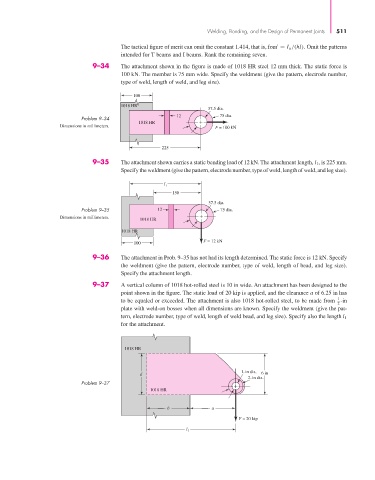
9–34 The attachment shown in the figure is made of 1018 HR steel 12 mm thick. The static force is
100 kN. The member is 75 mm wide. Specify the weldment (give the pattern, electrode number,
type of weld, length of weld, and leg size).
100
1018 HR
37.5 dia.
12 75 dia.
Problem 9–34
1018 HR
Dimensions in millimeters. F = 100 kN
225
9–35 The attachment shown carries a static bending load of 12 kN. The attachment length, l 1 , is 225 mm.
Specify the weldment (give the pattern, electrode number, type of weld, length of weld, and leg size).
l 1
150
37.5 dia.
Problem 9–35 12 75 dia.
Dimensions in millimeters.
1018 HR
1018 HR
F = 12 kN
100
9–36 The attachment in Prob. 9–35 has not had its length determined. The static force is 12 kN. Specify
the weldment (give the pattern, electrode number, type of weld, length of bead, and leg size).
Specify the attachment length.
9–37 A vertical column of 1018 hot-rolled steel is 10 in wide. An attachment has been designed to the
point shown in the figure. The static load of 20 kip is applied, and the clearance a of 6.25 in has
1
to be equaled or exceeded. The attachment is also 1018 hot-rolled steel, to be made from -in
2
plate with weld-on bosses when all dimensions are known. Specify the weldment (give the pat-
tern, electrode number, type of weld, length of weld bead, and leg size). Specify also the length l 1
for the attachment.
1018 HR
1-in dia.
d 6 in
2-in dia.
Problem 9–37
1018 HR
b a
F = 20 kip
l 1