Page 535 - Shigley's Mechanical Engineering Design
P. 535

bud29281_ch09_475-516.qxd  12/16/2009  7:13 pm  Page 509 pinnacle 203:MHDQ196:bud29281:0073529281:bud29281_pagefiles:


                                                                         Welding, Bonding, and the Design of Permanent Joints  509

                                                                 F
                                                          h
                             Problems 9–17 to 9–20
                                                 d
                                                     b
                                                           c


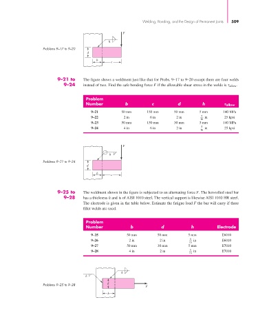
                                   9–21 to     The figure shows a weldment just like that for Probs. 9–17 to 9–20 except there are four welds
                                      9–24     instead of two. Find the safe bending force F if the allowable shear stress in the welds is τ allow .


                                                Problem
                                                Number            b           c          d          h           allow

                                                  9–21          50 mm      150 mm      50 mm       5 mm      140 MPa
                                                  9–22           2 in        6 in       2 in        5  in     25 kpsi
                                                                                                   16
                                                  9–23          50 mm      150 mm      30 mm       5 mm      140 MPa
                                                  9–24           4 in        6 in       2 in        5  in     25 kpsi
                                                                                                   16


                                                                 F
                                                           h
                             Problems 9–21 to 9–24
                                                d
                                                     b
                                                           c


                                   9–25 to     The weldment shown in the figure is subjected to an alternating force F. The hot-rolled steel bar
                                      9–28     has a thickness h and is of AISI 1010 steel. The vertical support is likewise AISI 1010 HR steel.
                                               The electrode is given in the table below. Estimate the fatigue load F the bar will carry if three
                                               fillet welds are used.


                                                Problem
                                                Number              b             d            h           Electrode
                                                  9–25            50 mm         50 mm         5 mm           E6010
                                                  9–26             2 in          2 in          5  in         E6010
                                                                                              16
                                                  9–27            50 mm         30 mm         5 mm           E7010
                                                  9–28             4 in          2 in          5  in         E7010
                                                                                              16


                                                                h
                                                h

                             Problems 9–25 to 9–28        d
                                                                           F
                                                          b
   530   531   532   533   534   535   536   537   538   539   540