Page 531 - Shigley's Mechanical Engineering Design
P. 531

bud29281_ch09_475-516.qxd  12/16/2009  7:13 pm  Page 505 pinnacle 203:MHDQ196:bud29281:0073529281:bud29281_pagefiles:


                                                                         Welding, Bonding, and the Design of Permanent Joints  505
                       Figure 9–28

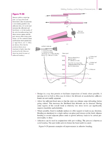
                       Stresses within a single-lap                            (a)
                       joint. (a) Lap-joint tensile
                       forces have a line of action that
                       is not initially parallel to the
                       adherend sides. (b) As the load
                                                                               (b)
                       increases the adherends and
                       bond bend. (c) In the locality of
                                                                                            Peel and
                       the end of an adherend peel and
                                                                                          shear stresses
                       shear stresses appear, and the
                       peel stresses often induce joint
                       failure. (d) The seminal Goland
                       and Reissner stress predictions
                       (J. Appl. Mech., vol. 77, 1944)
                                                                               (c)
                       are shown. (Note that the
                       predicted shear-stress        ASTM D 1002-94
                       maximum is higher than that
                       predicted by the Volkersen    l = 0.5 in (12.7 mm)
                                                     t = 0.064 in (1.6 mm)
                       shear-lag model because of    Aluminum: E = 10 Msi (70 GPa)  Stress (psi)
                       adherend bending.)            Epoxy: E a  = 500 ksi (3.5 GPa)
                                                                          10000                         , Goland and
                                                                                 Stresses shown for an  Reissner
                                                                                 applied load of
                                                                           8000  P = 1000 lbf (4.4 kN)
                                                                                                        , Goland and
                                                                                 Note: For very long joints,
                                                                           6000  Volkersen predicts only 50% of  Reissner
                                                                                 the G-R shear stress.
                                                                           4000                         , Volkersen

                                                                           2000                        ave

                                                                                                      x (in)
                                                             −0.2     −0.1            0.1      0.2
                                                                          −2000
                                                                             (d)


                                               • Design in a way that permits or facilitates inspections of bonds where possible. A
                                                 missing rivet or bolt is often easy to detect, but debonds or unsatisfactory adhesive
                                                 bonds are not readily apparent.
                                               • Allow for sufficient bond area so that the joint can tolerate some debonding before
                                                 going critical. This increases the likelihood that debonds can be detected. Having
                                                 some regions of the overall bond at relatively low stress levels can significantly
                                                 improve durability and reliability.
                                               • Where possible, bond to multiple surfaces to offer support to loads in any direction.
                                                 Bonding an attachment to a single surface can place peel stresses on the bond, whereas
                                                 bonding to several adjacent planes tends to permit arbitrary loads to be carried pre-
                                                 dominantly in shear.
                                               • Adhesives can be used in conjunction with spot welding. The process is known as
                                                 weld bonding. The spot welds serve to fixture the bond until it is cured.
                                                  Figure 9–29 presents examples of improvements in adhesive bonding.
   526   527   528   529   530   531   532   533   534   535   536