
Page 527 - Shigley's Mechanical Engineering Design
P. 527
bud29281_ch09_475-516.qxd 12/16/2009 7:13 pm Page 501 pinnacle 203:MHDQ196:bud29281:0073529281:bud29281_pagefiles:
Welding, Bonding, and the Design of Permanent Joints 501
Figure 9–25 (a)
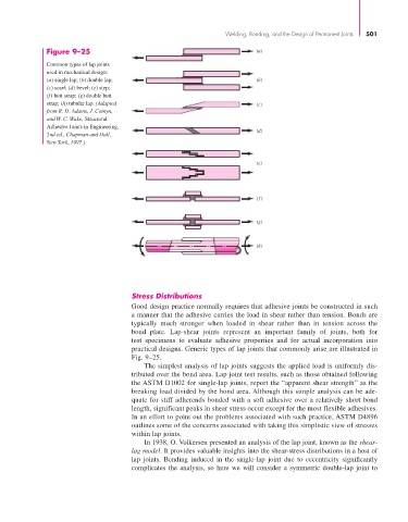
Common types of lap joints
used in mechanical design:
(a) single lap; (b) double lap; (b)
(c) scarf; (d) bevel; (e) step;
(f) butt strap; (g) double butt
strap; (h) tubular lap. (Adapted (c)
from R. D. Adams, J. Comyn,
and W. C. Wake, Structural
Adhesive Joints in Engineering,
(d)
2nd ed., Chapman and Hall,
New York, 1997.)
(e)
( f)
(g)
(h)
Stress Distributions
Good design practice normally requires that adhesive joints be constructed in such
a manner that the adhesive carries the load in shear rather than tension. Bonds are
typically much stronger when loaded in shear rather than in tension across the
bond plate. Lap-shear joints represent an important family of joints, both for
test specimens to evaluate adhesive properties and for actual incorporation into
practical designs. Generic types of lap joints that commonly arise are illustrated in
Fig. 9–25.
The simplest analysis of lap joints suggests the applied load is uniformly dis-
tributed over the bond area. Lap joint test results, such as those obtained following
the ASTM D1002 for single-lap joints, report the “apparent shear strength” as the
breaking load divided by the bond area. Although this simple analysis can be ade-
quate for stiff adherends bonded with a soft adhesive over a relatively short bond
length, significant peaks in shear stress occur except for the most flexible adhesives.
In an effort to point out the problems associated with such practice, ASTM D4896
outlines some of the concerns associated with taking this simplistic view of stresses
within lap joints.
In 1938, O. Volkersen presented an analysis of the lap joint, known as the shear-
lag model. It provides valuable insights into the shear-stress distributions in a host of
lap joints. Bending induced in the single-lap joint due to eccentricity significantly
complicates the analysis, so here we will consider a symmetric double-lap joint to