
Page 528 - Shigley's Mechanical Engineering Design
P. 528
bud29281_ch09_475-516.qxd 12/16/2009 7:13 pm Page 502 pinnacle 203:MHDQ196:bud29281:0073529281:bud29281_pagefiles:
502 Mechanical Engineering Design
Figure 9–26 P
2 P
P
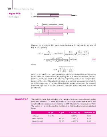
Double-lap joint.
2
(a)
y
t o l l
2 2
t i
t h x
o
h
(b)
illustrate the principles. The shear-stress distribution for the double lap joint of
Fig. 9–26 is given by
Pω Pω 2E o t o − E i t i
τ(x) = cosh(ωx) +
4b sinh(ωl/2) 4b cosh(ωl/2) 2E o t o + E i t i
(α i − α o ) Tω
+ sinh(ωx) (9–7)
(1/E o t o + 2/E i t i ) cosh(ωl/2)
where
G 1 2
ω = +
h E o t o E i t i
and E o , t o , α o , and E i , t i , α i , are the modulus, thickness, coefficient of thermal expansion
for the outer and inner adherend, respectively; G, h, b, and l are the shear modulus,
thickness, width, and length of the adhesive, respectively; and T is a change in tem-
perature of the joint. If the adhesive is cured at an elevated temperature such that the
stress-free temperature of the joint differs from the service temperature, the mismatch
in thermal expansion of the outer and inner adherends induces a thermal shear across
the adhesive.
EXAMPLE 9–7 The double-lap joint depicted in Fig. 9–26 consists of aluminum outer adherends and an
inner steel adherend. The assembly is cured at 250°F and is stress-free at 200°F. The
completed bond is subjected to an axial load of 2000 lbf at a service temperature of 70°F.
The width b is 1 in, the length of the bond l is 1 in. Additional information is tabulated
below:
G, psi E, psi , in/(in . °F) Thickness, in
−6
6
Adhesive 0.2(10 ) 55(10 ) 0.020
−6
6
Outer adherend 10(10 ) 13.3(10 ) 0.150
−6
6
Inner adherend 30(10 ) 6.0(10 ) 0.100