
Page 529 - Shigley's Mechanical Engineering Design
P. 529
bud29281_ch09_475-516.qxd 12/16/2009 7:13 pm Page 503 pinnacle 203:MHDQ196:bud29281:0073529281:bud29281_pagefiles:
Welding, Bonding, and the Design of Permanent Joints 503
Sketch a plot of the shear stress as a function of the length of the bond due to (a) thermal
stress, (b) load-induced stress, and (c) the sum of stresses in a and b; and (d) find where
the largest shear stress is maximum.
Solution In Eq. (9–7) the parameter ω is given by
G 1 2
ω = +
h E o t o E i t i
6
0.2(10 ) 1 2 −1
= + = 3.65 in
6
6
0.020 10(10 )0.15 30(10 )0.10
−6
−6
−6
(a) For the thermal component, α i − α o = 6(10 ) − 13.3(10 ) =−7.3(10 )
in (in °F), T = 70 − 200 =−130 F,
◦
(α i − α o ) Tω sinh(ωx)
τ th (x) =
(1/E o t o + 2/E i t i ) cosh(ωl/2)
−6
−7.3(10 )(−130)3.65 sinh(3.65x)
1 2 3.65(1)
τ th (x) =
10(10 )0.150 + 30(10 )0.100 cosh 2
6
6
= 816.4 sinh(3.65x)
The thermal stress is plotted in Fig. (9–27) and tabulated at x =−0.5, 0, and 0.5 in the
table below.
(b) The bond is “balanced” (E o t o = E i t i /2), so the load-induced stress is given by
Pω cosh(ωx) 2000(3.65) cosh(3.65x)
τ P (x) = = = 604.1 cosh(3.65x) (1)
4b sinh(ωl/2) 4(1)3.0208
The load-induced stress is plotted in Fig. (9–27) and tabulated at x =−0.5, 0, and 0.5
in the table below.
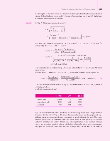
(c) Total stress table (in psi):
( 0.5) (0) (0.5)
Thermal only −2466 0 2466
Load-induced only 1922 604 1922
Combined −544 604 4388
(d) The maximum shear stress predicted by the shear-lag model will always occur at
the ends. See the plot in Fig. 9–27. Since the residual stresses are always present, sig-
nificant shear stresses may already exist prior to application of the load. The large
stresses present for the combined-load case could result in local yielding of a ductile
adhesive or failure of a more brittle one. The significance of the thermal stresses
serves as a caution against joining dissimilar adherends when large temperature
changes are involved. Note also that the average shear stress due to the load is