
Page 530 - Shigley's Mechanical Engineering Design
P. 530
bud29281_ch09_475-516.qxd 12/16/2009 7:13 pm Page 504 pinnacle 203:MHDQ196:bud29281:0073529281:bud29281_pagefiles:
504 Mechanical Engineering Design
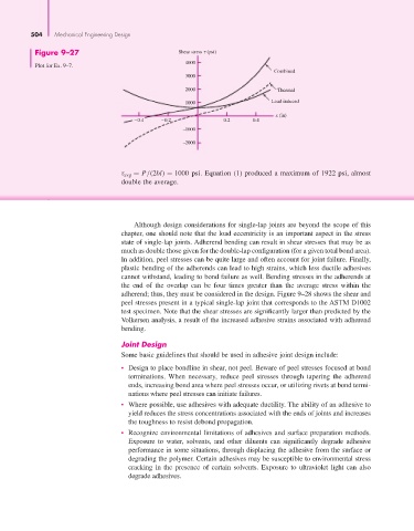
Figure 9–27 Shear stress (psi)
Plot for Ex. 9–7. 4000
Combined
3000
2000 Thermal
1000 Load induced
x (in)
−0.4 −0.2 0.2 0.4
−1000
−2000
τ avg = P/(2bl) = 1000 psi. Equation (1) produced a maximum of 1922 psi, almost
double the average.
Although design considerations for single-lap joints are beyond the scope of this
chapter, one should note that the load eccentricity is an important aspect in the stress
state of single-lap joints. Adherend bending can result in shear stresses that may be as
much as double those given for the double-lap configuration (for a given total bond area).
In addition, peel stresses can be quite large and often account for joint failure. Finally,
plastic bending of the adherends can lead to high strains, which less ductile adhesives
cannot withstand, leading to bond failure as well. Bending stresses in the adherends at
the end of the overlap can be four times greater than the average stress within the
adherend; thus, they must be considered in the design. Figure 9–28 shows the shear and
peel stresses present in a typical single-lap joint that corresponds to the ASTM D1002
test specimen. Note that the shear stresses are significantly larger than predicted by the
Volkersen analysis, a result of the increased adhesive strains associated with adherend
bending.
Joint Design
Some basic guidelines that should be used in adhesive joint design include:
• Design to place bondline in shear, not peel. Beware of peel stresses focused at bond
terminations. When necessary, reduce peel stresses through tapering the adherend
ends, increasing bond area where peel stresses occur, or utilizing rivets at bond termi-
nations where peel stresses can initiate failures.
• Where possible, use adhesives with adequate ductility. The ability of an adhesive to
yield reduces the stress concentrations associated with the ends of joints and increases
the toughness to resist debond propagation.
• Recognize environmental limitations of adhesives and surface preparation methods.
Exposure to water, solvents, and other diluents can significantly degrade adhesive
performance in some situations, through displacing the adhesive from the surface or
degrading the polymer. Certain adhesives may be susceptible to environmental stress
cracking in the presence of certain solvents. Exposure to ultraviolet light can also
degrade adhesives.