
Page 536 - Shigley's Mechanical Engineering Design
P. 536
bud29281_ch09_475-516.qxd 12/16/2009 7:13 pm Page 510 pinnacle 203:MHDQ196:bud29281:0073529281:bud29281_pagefiles:
510 Mechanical Engineering Design
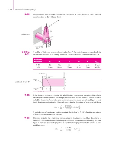
9–29 The permissible shear stress for the weldment illustrated is 20 kpsi. Estimate the load, F, that will
cause this stress in the weldment throat.
F
8 in
Problem 9–29
3 in
1 in
4
9–30 to A steel bar of thickness h is subjected to a bending force F. The vertical support is stepped such that
9–31 the horizontal welds are b 1 and b 2 long. Determine F if the maximum allowable shear stress is τ allow .
Problem
Number b 1 b 2 c d h allow
9–30 2 in 4 in 6 in 4 in 5 in 25 kpsi
16
9–31 30 mm 50 mm 150 mm 50 mm 5 mm 140 MPa
F
b 1 h
h
Problems 9–30 to 9–31 d
c
h b 2
9–32 In the design of weldments in torsion it is helpful to have a hierarchical perception of the relative
efficiency of common patterns. For example, the weld-bead patterns shown in Table 9–1 can be
ranked for desirability. Assume the space available is an a × a square. Use a formal figure of merit
that is directly proportional to J and inversely proportional to the volume of weld metal laid down:
J 0.707hJ u J u
fom = = = 1.414
vol (h /2)l hl
2
A tactical figure of merit could omit the constant, that is, fom = J u /(hl). Rank the six patterns
of Table 9–1 from most to least efficient.
9–33 The space available for a weld-bead pattern subject to bending is a × a. Place the patterns of
Table 9–2 in hierarchical order of efficiency of weld metal placement to resist bending. A formal
figure of merit can be directly proportion to I and inversely proportional to the volume of weld
metal laid down:
I 0.707hI u I u
fom = = = 1.414
vol (h /2)l hl
2