
Page 106 -
P. 106
102 P.-O. Siebers and F. Klügl
Table 6.1 (continued)
Category Element Decision Justification
Social/Psychological Comparative Include Effective strategy to reduce
aspect feedback energy consumption in residential
building
Informative Include Effective strategy to remove
feedback barriers in performing specific
behaviour
Apportionment Include Potential strategy to reduce
level energy consumption in office
building
Freeriding Include Behaviour that differentiate two
apportionment strategy
Sanction Include Factor to encounter freeriding
behaviour
Anonymity Include Factor to encounter freeriding
behaviour
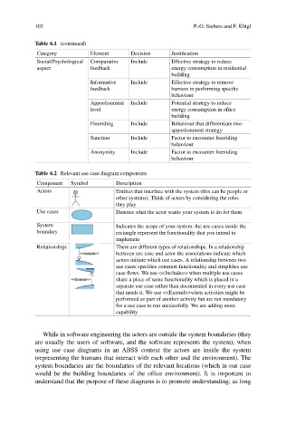
Table 6.2 Relevant use case diagram components
Component Symbol Description
Actors Entities that interface with the system (this can be people or
other systems). Think of actors by considering the roles
they play
Use cases Denotes what the actor wants your system to do for them
System Indicates the scope of your system: the use cases inside the
boundary rectangle represent the functionality that you intend to
implement
Relationships There are different types of relationships. In a relationship
between use case and actor the associations indicate which
actors initiate which use cases. A relationship between two
use cases specifies common functionality and simplifies use
case flows. We use <<Include>> when multiple use cases
share a piece of same functionality which is placed in a
separate use case rather than documented in every use case
that needs it. We use <<Extend>>when activities might be
performed as part of another activity but are not mandatory
for a use case to run successfully. We are adding more
capability
While in software engineering the actors are outside the system boundaries (they
are usually the users of software, and the software represents the system), when
using use case diagrams in an ABSS context the actors are inside the system
(representing the humans that interact with each other and the environment). The
system boundaries are the boundaries of the relevant locations (which in our case
would be the building boundaries of the office environment). It is important to
understand that the purpose of these diagrams is to promote understanding; as long