
Page 110 -
P. 110
106 P.-O. Siebers and F. Klügl
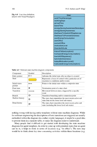
Fig. 6.4 User class definition
[drawn with Visual Paradigm]
Table 6.5 Relevant state machine diagram components
Component Symbol Description
Entry pointer Indicates the initial state after an object is created
State Represents a locus of control with a particular set of
reactions to conditions and/or events
Initial states Points to the initial state within a composite state
pointer
Final state Termination point of a state chart
Transition Movement between states, triggered by a specific
event
Branch Transition branching and/or connection point
Shallow history The state chart remembers the most recent active sub
state (but not the lower level sub-states)
Deep history The state chart remembers the most recent active sub
state (including the lower level sub states)
nothing wrong with having entity templates without state machine diagrams. While
for software engineering the descriptions of how transitions are triggered are usually
embedded within the diagram (in a rather cryptic language), it might be a good idea
to present them in a separate table, to make the diagram easier to understand.
Many people find it difficult to get started with developing the state machine
diagrams for agent templates. In order to come up with potential states that an agent
can be in, it helps to think in terms of locations (e.g. “in office”). The next step
would be to think about key time-consuming activities within these locations (e.g.