
Page 48 - Six Sigma for electronics design and manufacturing
P. 48
Six Sigma for Electronics Design and Manufacturing
18
DFM analysis results in reduced production time and need for oper-
ator skills. The DFM design guidelines, such as the ones mentioned
above, are based on common lessons learned while developing elec-
tronic products. Prior to formal DFM systems, checklists were being
used by major electronic companies as a repository for the collective
wisdom of their successful design engineers.
DFM design guidelines emphasize the design of electronic products
using self-locating and self-aligning parts, built on a suitable base
part. The number of parts should be minimized by using standard
parts and integrating functionality and utility. Several cost saving
techniques should be used, such as standard and automatic labeling,
self-diagnosis capability at the lowest level, and using symmetrical
and tangle-free part designs.
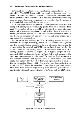
In the formal methodology of DFM, a scoring system is used to
measure the design efficiency, based on the performance objective
and the manufacturing capability. Several alternate designs can be
created using the principles of DFM, and the best design can then be
chosen based on the scoring system. A conceptual view of a DFM
scoring system is shown in Figure 1.5. A typical output of well-
designed DFM products is shown in Table 1.2, which compares the
design of a new product to older non-DFM designs. Such a product is
the Hewlett Packard (now Agilent) 34401A Multi-meter. This case
study was authored by Robert Williams and published in a book ed-
ited by the author (Shina, 1994). The product was designed using six
sigma and QFD. It can be seen that the number of parts and assem-
blies have been reduced significantly over previous generations of
multi-meters through the application of DFM as well as QFD princi-
Figure 1.5 Use of a DFM scoring system.