
Page 52 - Six Sigma for electronics design and manufacturing
P. 52
Six Sigma for Electronics Design and Manufacturing
22
The data flow, represented by an arrow, symbolizes the informa-
tion being carried from different parts of the systems in order to be
transformed or recorded. The name of the data flow should be writ-
ten alongside the arrow.
Every data flow and data store should have an associated data dic-
tionary, which provides a single document to record information nec-
essary to the understanding of the data flow diagrams. The informa-
tion can take the form of what records are kept for each data item and
the associated information for each record. The definition of each ele-
ment of process mapping is as follows:
Process—activities to satisfy customers’ requirements
Inputs—the material or data that is changed by the process
Outputs—the results of the operations of the process
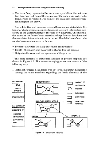
The basic elements of structured analysis or process mapping are
shown in Figure 1.6. The process mapping procedures consist of the
following steps:
1. Establish process boundaries (“as is” flow), including discussions
among the team members regarding the basic elements of the
Figure 1.6 Structured analysis.