
Page 184 -
P. 184
6.4 Application architectures 167
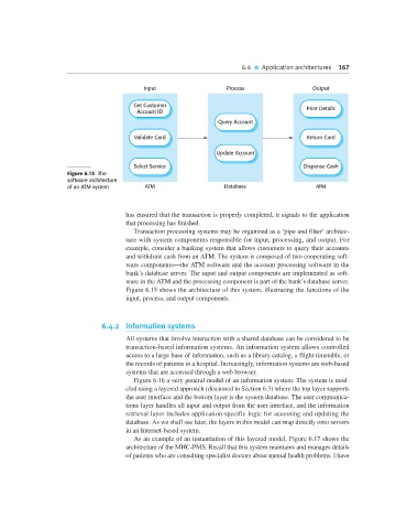
Input Process Output
Get Customer Print Details
Account ID
Query Account
Validate Card Return Card
Update Account
Select Service Dispense Cash
Figure 6.15 The
software architecture
of an ATM system ATM Database ATM
has ensured that the transaction is properly completed, it signals to the application
that processing has finished.
Transaction processing systems may be organized as a ‘pipe and filter’ architec-
ture with system components responsible for input, processing, and output. For
example, consider a banking system that allows customers to query their accounts
and withdraw cash from an ATM. The system is composed of two cooperating soft-
ware components—the ATM software and the account processing software in the
bank’s database server. The input and output components are implemented as soft-
ware in the ATM and the processing component is part of the bank’s database server.
Figure 6.15 shows the architecture of this system, illustrating the functions of the
input, process, and output components.
6.4.2 Information systems
All systems that involve interaction with a shared database can be considered to be
transaction-based information systems. An information system allows controlled
access to a large base of information, such as a library catalog, a flight timetable, or
the records of patients in a hospital. Increasingly, information systems are web-based
systems that are accessed through a web browser.
Figure 6.16 a very general model of an information system. The system is mod-
eled using a layered approach (discussed in Section 6.3) where the top layer supports
the user interface and the bottom layer is the system database. The user communica-
tions layer handles all input and output from the user interface, and the information
retrieval layer includes application-specific logic for accessing and updating the
database. As we shall see later, the layers in this model can map directly onto servers
in an Internet-based system.
As an example of an instantiation of this layered model, Figure 6.17 shows the
architecture of the MHC-PMS. Recall that this system maintains and manages details
of patients who are consulting specialist doctors about mental health problems. I have