
Page 330 -
P. 330
CHAPTER 12 ANALYSIS MODELING 301
By the mid-1980s, real-time "extensions" were introduced by Ward and Mellor
[WAR85] and later by Hatley and Pirbhai [HAT87]. These extensions resulted in a more
robust analysis method that could be applied effectively to engineering problems.
Attempts to develop one consistent notation have been suggested [BRU88], and mod-
ernized treatments have been published to accommodate the use of CASE tools
[YOU89].
12.2 THE ELEMENTS OF THE ANALYSIS MODEL
The analysis model must achieve three primary objectives: (1) to describe what the
customer requires, (2) to establish a basis for the creation of a software design, and
(3) to define a set of requirements that can be validated once the software is built. To
accomplish these objectives, the analysis model derived during structured analysis
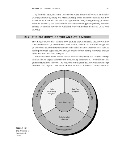
takes the form illustrated in Figure 12.1.
At the core of the model lies the data dictionary—a repository that contains descrip-
tions of all data objects consumed or produced by the software. Three different dia-
grams surround the the core. The entity relation diagram (ERD) depicts relationships
between data objects. The ERD is the notation that is used to conduct the data
description Process specification
object relationship Data flow
Entity
diagram
Data diagram (PSPEC)
Data dictionary
State-transition
diagram
FIGURE 12.1 Control specification
The structure of
the analysis
model