
Page 131 - Software and Systems Requirements Engineering in Practice
P. 131
i
g
l
C h a p t e r 4 :
e
n
t
n
M
s
r
i
e
e
m
u
o
d
R
q
e
C h a p t e r 4 : R e q u i r e m e n t s M o d e l i n g 99 99
4.6 Elicitation and Analysis Model Heuristics
This section describes a set of heuristics and guidelines for
requirements elicitation and analysis sessions when using the UML.
These heuristics have been successfully used on several of our larger
projects. Note that as heuristics and style guides for the UML have
been widely described elsewhere[Riel 1996], [Ambler 2005], the topic
will not be covered here. Rather, we have concentrated on heuristics
that are necessary for the construction of verifiable models and the
programmatic extraction of requirements.
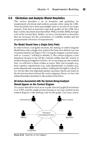
The Model Should Have a Single Entry Point
In order to force a navigable structure, the starting or context diagram
should have only a single entry point in the form of an abstract use case
or product feature (see Figure 4.14). Giving the diagram a special name,
such as “context,” will help to identify it. The context diagram is also
important because it has all the external entities that the system or
product being investigated will have. As we are using use case notation
here, we will refer to these entities as actors. They can be people (e.g.,
team captain), organizations (e.g., sales department), or systems (e.g.,
police department computer system). Getting the list right is critical, as
we will see later that important quality assurance checks are based on
the list of actors derived from the context diagram. Hence, we have the
related heuristics described in the sections that follow.
All Actors Associated with the System Being Analyzed
Should Appear on the Context Diagram
The model should be built as an acyclic directed graph [Crochemore
et al. 1997], and the single product feature or use case symbol on the
context diagram is the starting node for the graph. Use cases, actors,
Administrator Team Captain
Olympics
Scheduling System
Official Spectator
Competitor Judge
FIGURE 4.14 Example context diagram