
Page 134 - Software and Systems Requirements Engineering in Practice
P. 134
102 S o f t w a r e & S y s t e m s R e q u i r e m e n t s E n g i n e e r i n g : I n P r a c t i c e
Team
Management
Team
Management
Right Wrong
Add Team Add Team
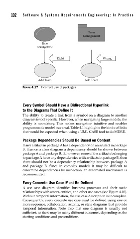
FIGURE 4.17 Incorrect use of packages
Every Symbol Should Have a Bidirectional Hyperlink
to the Diagrams That Define It
The ability to create a link from a symbol on a diagram to another
diagram is tool specific. However, when navigating large models, the
ability is mandatory. This makes navigation intuitive and enables
programmatic model traversal. Table 4.1 highlights the kinds of links
that would be expected when using a UML CASE tool to do MDRE.
Package Dependencies Should Be Based on Content
If any artifact in package A has a dependency on an artifact in package
B, then on a class diagram a dependency should be shown between
package A and package B. If, however, none of the artifacts belonging
to package A have any dependencies with artifacts in package B, then
there should not be a dependency relationship between package A
and package B. Since in complex models it may be difficult to
determine dependencies by inspection, an automated mechanism is
recommended.
Every Concrete Use Case Must Be Defined
A use case diagram identifies business processes and their static
relationships with actors, entities, and other use cases (see Figure 4.18).
Without temporal information, the use case description is incomplete.
Consequently, every concrete use case must be defined using one or
more sequence, collaboration, activity, or state diagrams that provide
temporal information. Note also that one diagram is usually not
sufficient, as there may be many different outcomes, depending on the
starting conditions and preconditions.