
Page 137 - Software and Systems Requirements Engineering in Practice
P. 137
105
C h a p t e r 4 :
R e q u i r e m e n t s M o d e l i n g
C h a p t e r 4 : R e q u i r e m e n t s M o d e l i n g 105
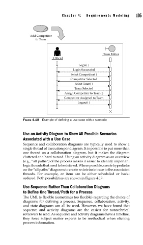
Add Competitor
to Team
: Team Editor
: Official
Login( )
Login Successful
Select Competitor( )
Competitor Selected
Select Team( )
Team Selected
Assign Competitor to Team( )
Competitor Assigned to Team
Logout( )
FIGURE 4.18 Example of defining a use case with a scenario
Use an Activity Diagram to Show All Possible Scenarios
Associated with a Use Case
Sequence and collaboration diagrams are typically used to show a
single thread of execution per diagram. It is possible to put more than
one thread on a collaboration diagram, but it makes the diagram
cluttered and hard to read. Using an activity diagram as an overview
(e.g., “all paths”) of the process makes it easier to identify important
logic threads that need to be defined. Where possible, create hyperlinks
on the “all paths” diagrams to create an intrinsic trace to the associated
threads. For example, an item can be either scheduled or back-
ordered. Both possibilities are shown in Figure 4.19.
Use Sequence Rather Than Collaboration Diagrams
to Define One Thread/Path for a Process
The UML is flexible (sometimes too flexible) regarding the choice of
diagrams for defining a process. Sequence, collaboration, activity,
and state diagrams can all be used. However, we have found that
sequence and activity diagrams are the easiest for nontechnical
reviewers to read. As sequence and activity diagrams have a timeline,
they force subject matter experts to be methodical when eliciting
process information.