
Page 140 - Software and Systems Requirements Engineering in Practice
P. 140
r
4
R e q u i r e m e n t s M o d e l i n g
:
e
a
p
h
t
C
C h a p t e r 4 : R e q u i r e m e n t s M o d e l i n g 107 107
Since the MDRE process starts with product features that become
use cases, when explaining them with sequence diagrams the objects
that communicate are initially not known (with the exception of
actors). During sequence diagram creation, objects necessary to
provide services are “discovered.” The objects are then placed as
classes on class diagrams and later organized by combining similar
classes or splitting classes that provide too many services or have
disjoint or unrelated services. Sequence diagrams force the early
discovery of objects, along with their associated classes and business
services. We have found that sequence diagrams are better for
elicitation services and sequence features, while activity diagrams do
a better job of illustrating complex logic.
Abstract Use Cases Must Be Realized with Included or
Inherited Concrete Use Cases
Abstract use cases represent product features that are at a very high
level (e.g., “power steering”) or can be a placeholder for sets of
processes (e.g., “manage teams”). They must be decomposed to sets
of features or processes that are testable.
The definition of a use case must be consistent across all diagrams
defining the use case. A use case shown on a use case diagram can
include other use cases and can optionally be extended by other use
cases. Included and extending use cases will appear on sequence
diagrams as messages to objects that will perform the requested
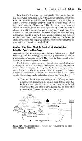
service. Consistency can be defined as follows (see Figure 4.20):
• There will be at least one message on a defining sequence
diagram with the same name as each included use case; that
is, how a use case fits into a process must be explained.
Otherwise, the use case is ambiguous; e.g., it uses other
processes but does not explain how they are used.
Driver Operate Window
<<include>> Selected
<<include>>
<<include>> Window
<<include>> Driver : Power Window Console
Jog Window Select Window( )
<<include>> <<include>> Down
Close <<include>> Open Window( )
Window Open Completely( )
Select
Window Jog Open
Open Unlock Window Up
Window Lock
Window Window
These functions must be
utilized
FIGURE 4.20 Semantic correctness requires that every concrete use case
must be used in a scenario.